TOLERANCJA polecenie
Otwiera okno dialogowe Tolerancja geometryczna.

Ikona: 
Opis
Otwiera okno dialogowe Tolerancja geometryczna w celu dodania symboli tolerancji do bieżącego rysunku.
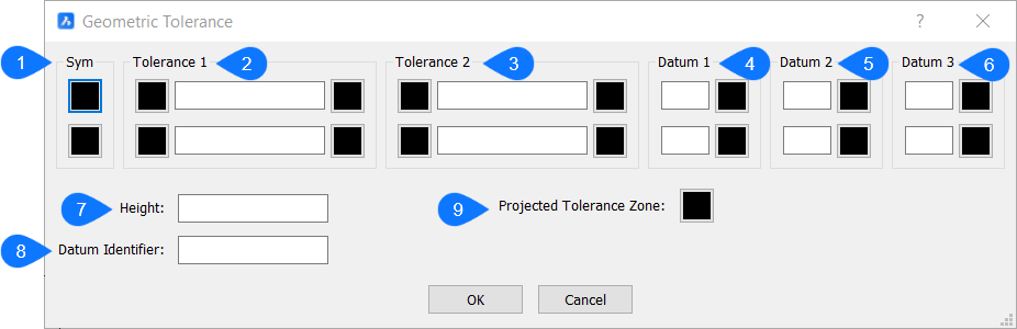
- Symbol
- Tolerancja 1
- Tolerancja 2
- Podstawa 1
- Podstawa 2
- Podstawa 3
Symbol
Określa symbol tolerancji w oknie dialogowym Symbol.
Tolerancja 1 & 2
Określa specyfikacje tolerancji (średnica, wartość i stan materiału).
- śreDnica
- Przełącza symbol średnicy.
- Wartość
- Określa wartość tolerancji.
- Stan Materiału
- Określa stan materiału w oknie dialogowym Stan materiału.
Datum 1, 2 & 3
Określa punkt odniesienia (wartość i stan materiału).
- Wartość
- Określa wartość punktu odniesienia.
- Stan Materiału
- Określa stan materiału w oknie dialogowym Stan materiału.
- WYSokość
- Określa wysokość symboli tolerancji.
- Identyfikator Podstawy
- Określa identyfikator układu odniesienia, taki jak Datum A.
- Strefa Projektowanej Tolerancji
- Przełącza symbol przewidywanej strefy tolerancji.
- Symbole tolerancji
-
Symbol Charakterystyka Typ 
Pozycja Lokalizacja 
Koncentryczność lub współosiowość Lokalizacja 
Symetria Lokalizacja 
Równoległość Orientacja 
Prostopadłość Orientacja 
Kanciastość Orientacja 
Cylindryczność Forma 
Płaskość Forma 
Okrągłość lub okrągłość Forma 
Prostoliniowość Forma 
Profil Powierzchni Profil 
Profil Linii Profil 
Bicie Promieniowe Ucieczka 
Bicie Całkowite Ucieczka
- Symbole stanu materiału
-
Symbol Definicja 
Przy maksymalnym stanie materiału (MMC) element zawiera maksymalną ilość materiału określoną w limitach. 
Przy najmniejszym stanie materiału (LMC) element zawiera minimalną ilość materiału określoną w limitach. 
Niezależnie od rozmiaru elementu (RFS) wskazuje, że element może mieć dowolny rozmiar w podanych granicach.