


BIM Typed Plan Editor dialog box
The BIM Typed Plan Editor dialog box allows you to edit the existing typed plans.
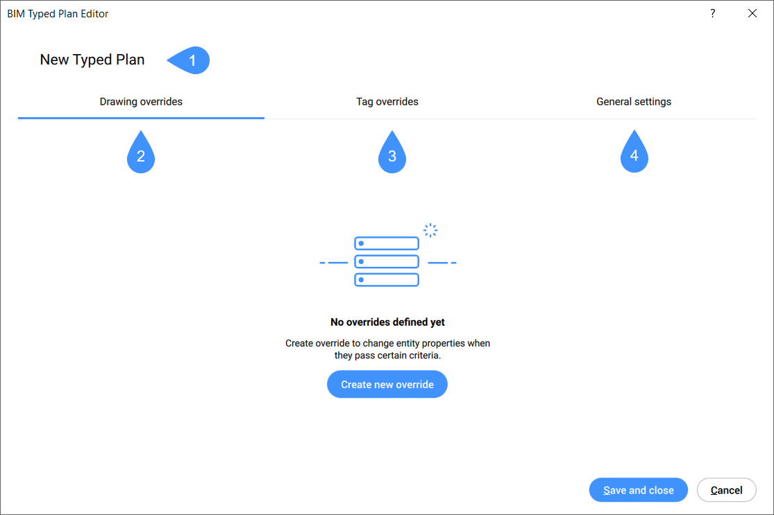
- Typed Plan name
- Drawing overrides
- Tag overrides
- General settings
Typed Plan name
Specifies the name of the selected Typed Plan to be edited. You can click on the selected Typed Plan name to rename it, then press Enter.
Drawing overrides
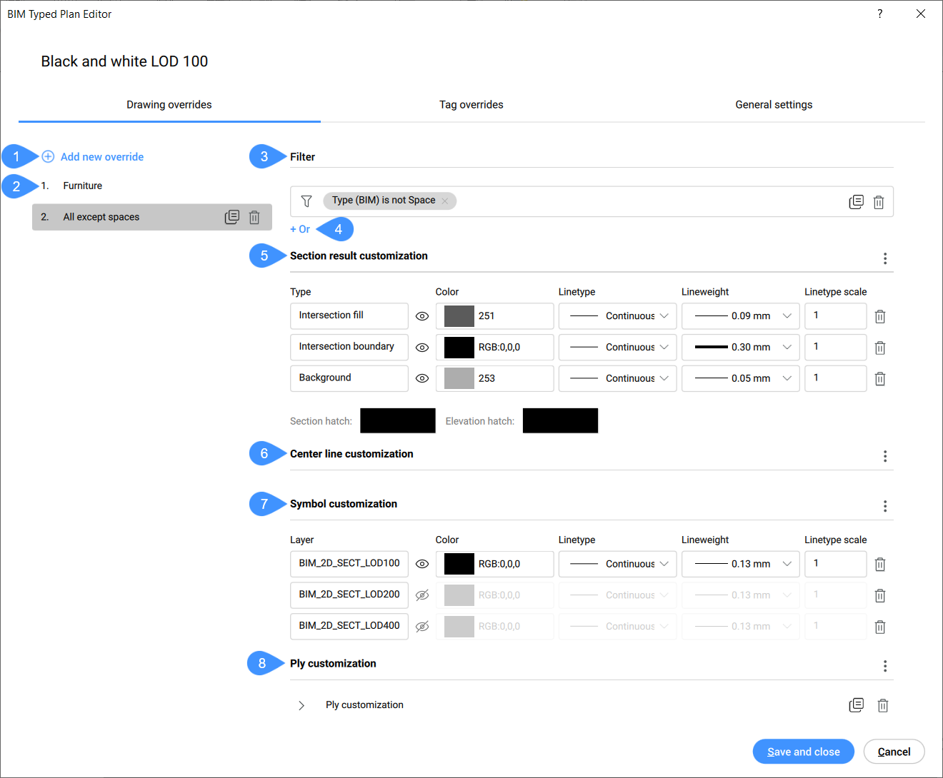
- Add new override
- Drawing overrides list
- Filter
- Add new filter
- Section result customization
- Center line customization
- Symbol customization
- Ply customization
- Add new override
- Adds a new override element to the list that functions as a top down entity filter. When an entity fits a criterion in the list, the rest of the overrides are no longer checked.
- Drawing overrides list
- Displays the hierarchically organized list of drawing overrides. You can rearrange the position of an override in the list by dragging and dropping it to the desired position.
- Filter
- Allows you to edit filter rules for drawing overrides by adding one or more parameter filters from the drop down list. Filter rows can be added to filter by multiple parameter combinations. These rows are separated using the logical "OR" operation. The rows can be copied by clicking the copy symbol or deleted by clicking the delete symbol.
- Add new filter row
- Click the + Or button to add a new filter row.
- Section result customization
- Allows you to customize how the lines of each element that is being processed by the section generation algorithm will turn out.
- Center Line customization
- Determines the appearance of the center of planar or linear entities. The resulting center lines, for example from cutting a wall’s center plane in a floorplan, can be customized.Note: There is no default setting to adjust the visibility of these center elements, and they are not normally displayed in section results.
- Symbol customization
- Click the context menu button to open the menu options:
- Ply customization
- Can be used to show only a certain type of plies in a plan view. An easy example is the visibility of only structural plies in a structural plan. Click the context menu button to open the menu options.
Tag Overrides
Tag overrides allow you to define the visualisation of entities containing specific tags. In the Tag overrides tab, preferences can be specified.
Note: When there is no tag defined for an object in the Typed Plan, the rules
set in _TagTypeToStyle.xml are used as fallback rules.
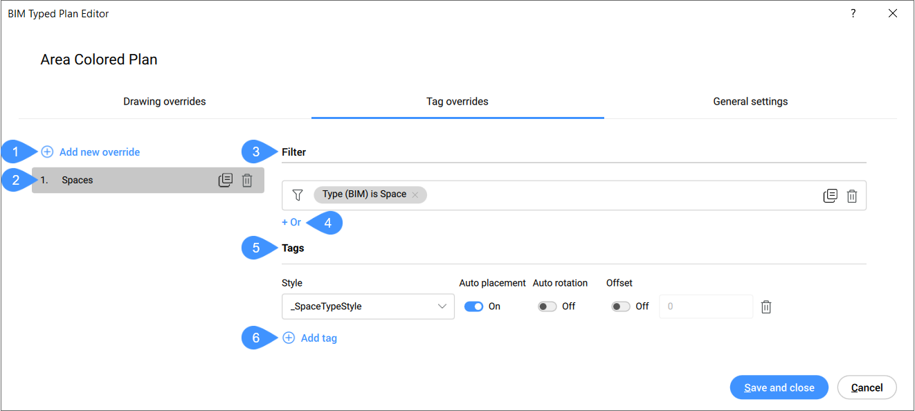
- Add New Override
- Tag overrides list
- Filter
- Add new filter row
- Tags
- Add tag
- Add new Override
- Creates a new tag override element to the list. By default, the template is named New override with the text highlighted. This highlighted override title can be modified by entering an custom name and pressing Enter to save and apply.
- Tag overrides list
- Displays the hierarchically organized list of tag overrides. You can rearrange the position of an override in the list by dragging and dropping it to the desired position.
- Filter
- Allows you to edit filter rules for tag overrides. It is similar with changing the filter rules for drawing overrides described above.
- Add new filter row
- Click the + Or button to add a new filter row.
- Tags
- Allows you to add and edit tag customizations. You can also deleted tag customizations. By
adding customizations for different entity types, customized styles can be defined including several
characteristics:
- Style
- Allows you to select the tag style.
- Auto placement
- Specifies whether the placement of the tag should be defined automatically or not.
- Auto Rotation
- Specifies whether the rotation of the tag should be defined automatically or not.
- Offset
- Specifies whether the tag should be placed either with offset or not as well as the numerical offset value.
- Add tag
- Allows you to add a new tag customization.
General settings
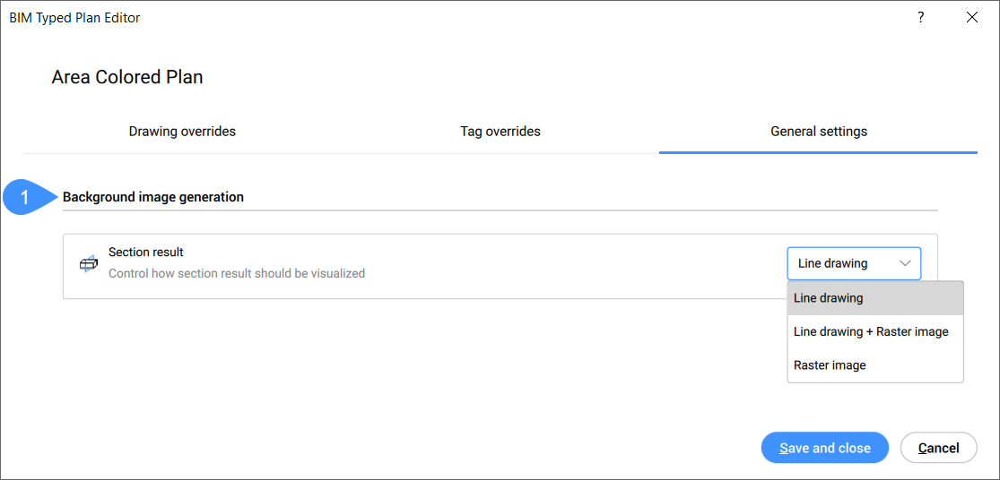
- Background image generation
- Background image generation
- Allows you to control how the section result should be visualized by selecting one option from
the drop-down menu:
- Line drawing: the section result is visualized as a line drawing.
- Line drawing + Raster image: the section result is visualized as a line drawing to which a background raster image is added.
- Raster image: the section result is visualized as a raster image.