TIN Definitions in TIN command
Overview
This article describes the TIN Definitions/operations that are created with the TIN Surface creation methods available in the TIN command. It also describes the dialog of each definition, where you can modify parameters.

Some of the operations, such as Create from faces, Add point clouds, and Create from contours are only used to create a new TIN Surface.
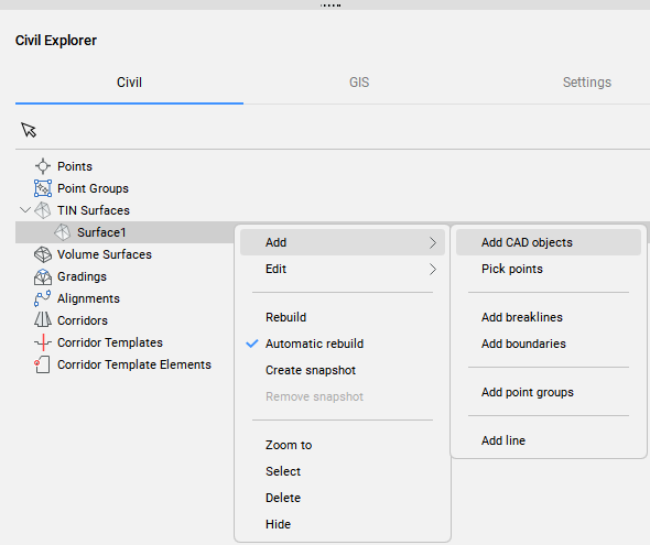
While other operations, such as Add drawing (CAD) objects, Add point, Add point groups can also be used to add data to existing TIN Surface. For easy access, these operations are also available in the Civil Explorer panel (see figure below).
Add drawing objects
The Add drawing objects definition creates a new TIN Surface or modifies an existing one from selected drawing/CAD objects.
To create the Add drawing object definition:
- Use the Select entities to create TIN surface option in the TIN command.
- Right-click an existing TIN Surface in the Civil Explorer and select Add CAD objects from the Add group.
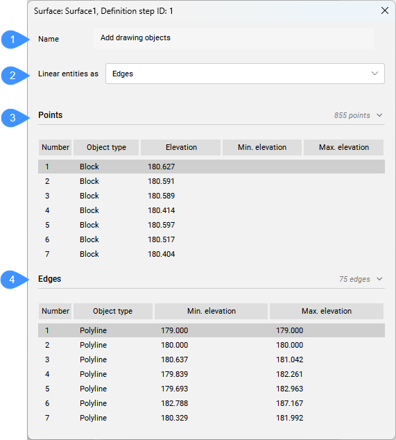
When you double-click the existing Add drawing objects definition in the Definitions tab of the Civil Explorer panel, the following dialog box opens.
- Name
- Linear entities as
- Points
- Edges
- Name
- Displays the TIN Surface definition name: Add drawing objects.
- Linear entities as
- Allows you to control how linear entities are applied to the TIN surface. You can choose between points and edges.
- Points
- Lists the points added to the TIN Surface as drawing objects. In addition to CAD points, also blocks, texts and Civil points are added to a TIN Surface as points. If the Points option is selected for polylines added to the TIN surface as drawing objects, the vertices of the polylines are also added to the TIN surface as points.Note: The entities that could be added with Add Points option are points, Civil points, lines, or polylines.
- Edges
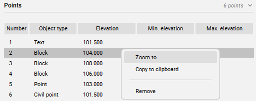
- Lists the linear entities that are applied to TIN Surface as triangles edges.Note: Right-click the object in the dialog box to open a context menu:
- Zoom to: zooms to the object in the drawing.
- Copy to clipboard: copies the geometry information.
- Remove: removes the object from the TIN Surface definition.
Min. and Max. elevation: the min. and max. elevation of the 3D Polyline. If the min. and max. elevations match, then the object is 2D Polyline / Polyline.
Add point files
The Add point files definition creates a TIN Surface from a selected point file.
It allows the simplification of points from the source point file while maintaining high accuracy in user-defined areas of the TIN Surface where more accurate terrain data is required.
To create the Add point files definition:
- select the Import from file option in the TIN command.
When you double-click this definition in the Definitions tab of the Civil Explorer panel, the following dialog box opens.
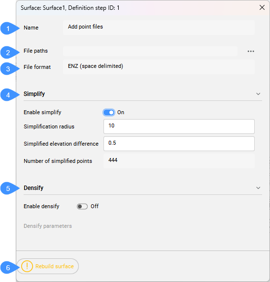
- Name
- File paths
- File format
- Simplify
- Densify
- Rebuild surface
- Name
- Displays the TIN Surface definition name: Add point files.
- File paths
- Displays the file path. Press the browse button to open the Select surface file dialog box.
- File format
- Displays the file format used for importing point file.
- Simplify
- Simplifies the TIN surface.
- Densify
- Densifies the TIN surface.
-
- Enable densify
- When enabled, it displays the file format used for importing point file.
- Densify parameters:
-
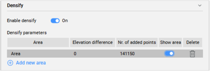
- Elevation difference
- Specified maximum elevation difference between the simplified TIN Surface and the excluded input points on a specified area in a TIN Surface.
- Number of added points
- Displays the number of points that have an elevation difference greater than the specified maximum value, and are consequently added back to the simplified TIN Surface.
- Show area
- If enabled, it highlights the specified densification area in a drawing.
- Delete
- Enables to delete the densification area.
- Rebuild surface
- Rebuilds the surface.
Add point
The Add point definition creates a new TIN Surface or modifies an existing one based on specified locations and elevations of the TIN points.
To create the Add point definition:
- Select the place Points option in the TIN command.
- Right-click an existing TIN Surface in the Civil Explorer and select Pick points option from the Add group.
When you double-click the Add point definition in the Definitions tab of the Civil Explorer panel, the following dialog box opens.
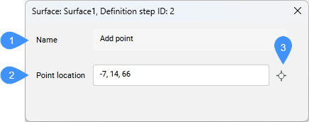
- Name
- Point location
- Pick point
- Name
- Displays the TIN Surface definition name: Add point.
- Point location
- Displays the point coordinates.
- Pick point
- Allows you to pick a new location and set a new point elevation.
Create from faces
The Create from faces definition creates a new TIN Surface from the selected 3D Face elements.
To create the Create from faces definition:
- select the create from Faces option in the TIN command.
When you double-click this definition in the Definitions tab of the Civil Explorer panel, the following dialog box opens.
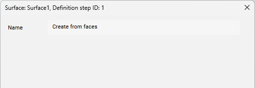
- Name
- Displays the surface definition name: Create from faces.
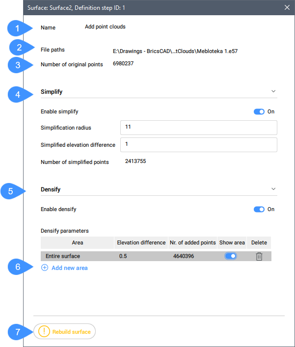
Add point clouds
The Create from Point Cloud definition creates a TIN Surface from a selected Point Cloud.
It allows the simplification of points from the source Point Cloud while maintaining high precision in user-defined areas of the TIN Surface where more accurate terrain data is required.
The Remove outer edges and Create snapshot definitions are automatically added to the TIN Surface after this operation.
To create the Add point clouds definition:
- select the create from point Cloud option in the TIN command.
When you double-click this definition in the Definitions tab of the Civil Explorer panel, the following dialog box opens.
- Name
- File paths
- Number of original points
- Simplify
- Densify
- Add new area
- Rebuild surface
- Name
- Displays the TIN Surface definition name: Add point clouds.
- File paths
- Displays the input file path.
- Number of original points
- Displays the number of original points in the point clouds.
- Simplify
- Simplifies the TIN surface.
- Densify
- Densifies the surface.
- Add new area
- Adds a new densification area. It requires to enter the elevation difference in the Command line and then select an existing or draw a new polygon in the drawing.
- Rebuild surface
- Rebuilds the TIN surface.
Add point groups
The Add point groups definition adds Civil points from a specified Point Groups to the existing TIN Surface or creates a new TIN Surface from specified Point Groups.
To create the Add point groups definition:
- Select the create from point Groups option in the TIN command.
- Right-click an existing TIN Surface in Civil Explorer panel and select Add point groups from the Add group.
The Remove outer edges definition is automatically added to the TIN Surface after this operation.
When you double-click this definition in the Definitions tab of the Civil Explorer panel, the following dialog box opens.
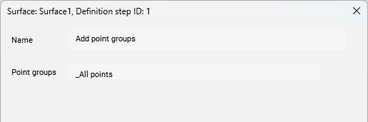
- Name
- Displays the surface definition name: Add point groups.
- Point groups
- Displays a list of Point groups used to create TIN Surface.
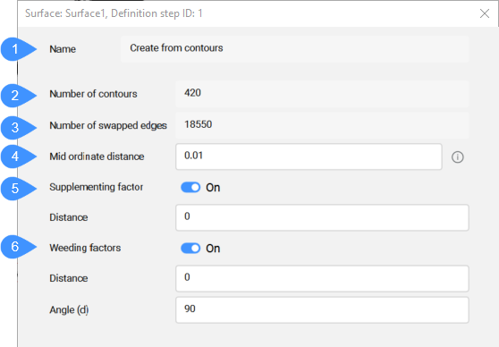
Create from Contours
The Create from Contours definition creates a TIN Surface from selected line entities. The density of points on contours taken for triangulation can be managed by specifying weeding and supplementing factors. When the input data includes arcs, the accuracy of TIN point along arcs depends on the Mid-ordinate distance parameter.
This method automatically minimizes flat triangles by swapping TIN edges.
To create the Create from Contours definition:
- select the create from cOntours option in the TIN command.
The Remove outer edges definition is automatically added to the TIN Surface after this operation.
When you double-click this definition in the Definitions tab of the Civil Explorer panel, the following dialog box opens.
- Name
- Number of contours
- Number of swapped edges
- Mid-ordinate distance
- Supplementing factor
- Weeding factor
- Name
- Displays the TIN Surface definition name: Create from contours.
- Number of contours
- Displays the number of the contours.
- Number of swapped edges
- Displays the number of the swapped edges.
- Mid-ordinate distance
- Adds supplementary TIN points along the arc according to the mid-ordinate distance which is used for arc approximation.
- Supplementing factor
- Toggles the using of supplementing factor.
- Weeding factor
- Toggles the using of weeding factor.
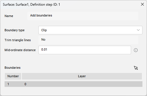
Clip polygon
If you select the cLip polygon option in the TIN command, a new Clip Boundary is added to the TIN Surface as an Add boundaries definition.
When you double-click this definition in the Definitions tab of the Civil Explorer panel, the following dialog box opens.