


AMSURFSYM command
Creates a surface symbol.

Icon: 
Methods
Select the object to attach the surface symbol and specify the points for its location.
- There are two use cases:
-
- When creating a new drawing that will contain mechanical
entities:
- Set the LOADMECHANICAL2D system variable to ON (1).
- Start a new drawing using a Mechanical2d template.
- When opening a drawing that contains mechanical
entities
- Set the LOADMECHANICAL2D system variable to ON (1).
- Open an existent ACM drawing and start special symbols creation.
- When creating a new drawing that will contain mechanical
entities:
Note: These symbols are compatible with the legacy AutoCAD
Mechanical application.
Note: The symbol will be added to the AM_5 layer.
Note: After opening a drawing that contains mechanical
entities, filling other drawings with mechanical-related data will be done
on-demand in contrast to previous versions. It will be possible when a user
copies the mechanical-related entities to the vanilla drawing. In the case of
copying, entities that are not related to the mechanical data, a vanilla drawing
will not be filled with mechanical data.
After creating the symbol prototype with the AMSURFSYM command, the user can configure the exact surface symbol's properties in the Properties panel:
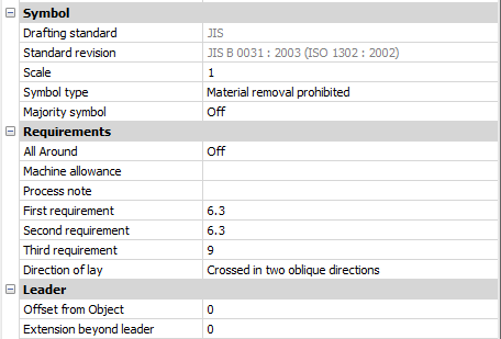
Note: The surface symbol properties depend on the used
standard.
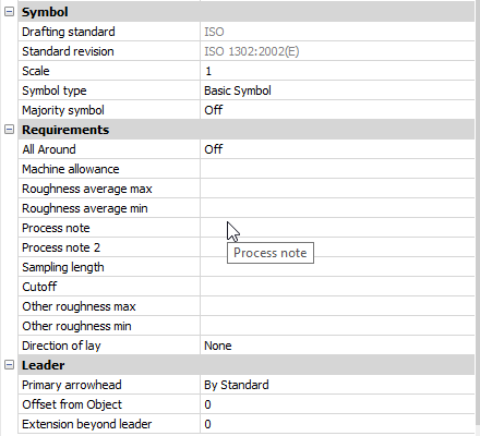
Symbol
- Symbol type
- Choose one of the:
-
- Basic symbol

- Material removal required

- Material removal prohibited

- Basic symbol
- Majority symbol
- Indicates the common state to all surfaces using a single collective indication symbol.
Requirements
- All Around
- Toggles the visibility of the All Around surface texture in the symbol.
- Machine allowance
- Specifies the machining allowance for the surface.
- Process note
- Defines the process requirements for the surface.
- First requirement
- Defines the first requirement for the surface.
- Second requirement
- Defines the second requirement for the surface.
- Third requirement
- Defines the third requirement for the surface.
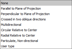
- Direction of lay
-
Sets the direction of lay for the surface.
-
- Roughness average max
- Defines the maximum roughness average for the surface.
- Roughness average min
- Defines the minimum roughness average for the surface.
- Process note2
- Defines the process requirements for the surface.
- Sampling length
- Defines the sampling length required for the surface.
- Other roughness max
- Defines the maximum other roughness for the surface.
- Other roughness min
- Defines the minimum other roughness for the surface.
Leader
- Offset from Object
- Specifies the distance between the extension line’s start point and the attached object.
- Extension beyond leader
- Specifies the distance between the symbol’s start point and the surface extension line’s end point.