


Comando ALLINEAMENTOELEMENTOTRA
Crea un nuovo elemento tra due elementi dell'allineamento selezionati.

Icona: 
Descrizione
A seconda del tipo selezionato del nuovo elemento, alcuni parametri dell'elemento vengono mantenuti quando vengono modificati gli elementi di associazione.
Tra due elementi esistenti è possibile creare i seguenti tipi di nuovi elementi: linee, curve, spirali, combinazioni spirale-curva-spirale, combinazioni spirale-spirale e le combinazioni spirale-linea-spirale.
Opzioni all'interno del comando
- Linea
- Crea un nuovo elemento linea tra due elementi curva esistenti. La nuova linea viene disegnato tangenzialmente a entrambi gli elementi di collegamento. La tangenza viene mantenuta quando gli elementi di attacco vengono modificati.La linea può essere aggiunta tra le seguenti combinazioni di elementi:
- Tra due cerchi non vincolati esistenti.
- Tra due cerchi vincolati esistenti come parte di combinazioni, ad esempio una Curva con Spirale e una combinazione Curva-Spirale-Spirale.
- Tra un cerchio esistente non vincolato e vincolato.
Note: Il modo in cui viene tracciata la linea tra gli elementi selezionati dipende dalle loro direzioni.
- Curve
- Crea un nuovo elemento curva tra due elementi di allineamento esistenti. La nuova curva viene disegnata tangenzialmente a entrambi gli elementi di collegamento. La tangenza e il raggio della curva vengono mantenuti quando si modificano gli elementi di attacco.
La posizione dei punti sugli elementi (di attacco) tra i quali viene creata una nuova curva e la lunghezza della curva vengono regolate in base alla modifica degli elementi di associazione.
La curva può essere aggiunta tra tutte le combinazioni di elementi, a eccezione del primo elemento selezionato e della spirale vincolata.
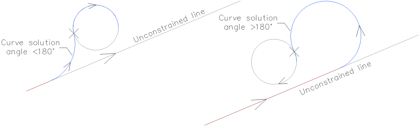
Note: La curva è definita dal tipo di elementi di attacco, dal raggio di curvatura specificato e dall'angolo di soluzione (< or >180°). Il modo in cui il cerchio viene disegnato tra gli elementi selezionati dipende dalla direzione degli elementi di attacco.
- Spirale
- Crea un nuovo elemento a spirale tra due elementi di allineamento esistenti. La nuova spirale viene disegnata tangenzialmente a entrambi gli elementi di attacco. La tangenza viene mantenuta quando gli elementi di attacco vengono modificati.Note: Una spirale libera è definita dal tipo e dalla direzione degli elementi di attacco selezionati. Poiché la spirale ha una sola soluzione geometrica, l'utente non può specificare parametri, ad esempio il parametro A o la lunghezza della spirale.
- Spirale-Curva-Spirale
- Crea una nuova combinazione spirale-curva-spirale tra due elementi di allineamento esistenti. La nuova combinazione viene disegnata tangenzialmente a entrambi gli elementi di collegamento. La tangenza, il raggio di curvatura ed entrambe le lunghezze della spirale vengono mantenuti quando si modificano gli elementi di attacco.
La posizione dei punti sugli elementi (di attacco) tra i quali viene creata una nuova combinazione e la lunghezza della curva vengono regolate in base alla modifica degli elementi di attacco.
Selezionare gli elementi di associazione, specificare il raggio della curva e le lunghezze della spirale per aggiungere la combinazione spirale-curva-spirale tra gli elementi dell'allineamento selezionati.
- Spirale-Spirale
- Crea una nuova combinazione di spirale-spirale tra due elementi di curva esistenti con lo stesso orientamento e possibilmente raggi diversi. La nuova combinazione viene disegnata tangenzialmente a entrambi gli elementi di collegamento. La tangenza viene mantenuta quando gli elementi di attacco vengono modificati.
I parametri della spirale (lunghezza e parametro A) e la posizione dei punti sugli elementi (di attacco), tra i quali viene creata una nuova combinazione, vengono calcolati in base al rapporto A1/A2 (o L1/L2) specificato.
Note: La posizione dei punti sugli elementi (di attacco) tra i quali viene creata una nuova combinazione e la lunghezza della curva vengono regolate in base alla modifica degli elementi di attacco.
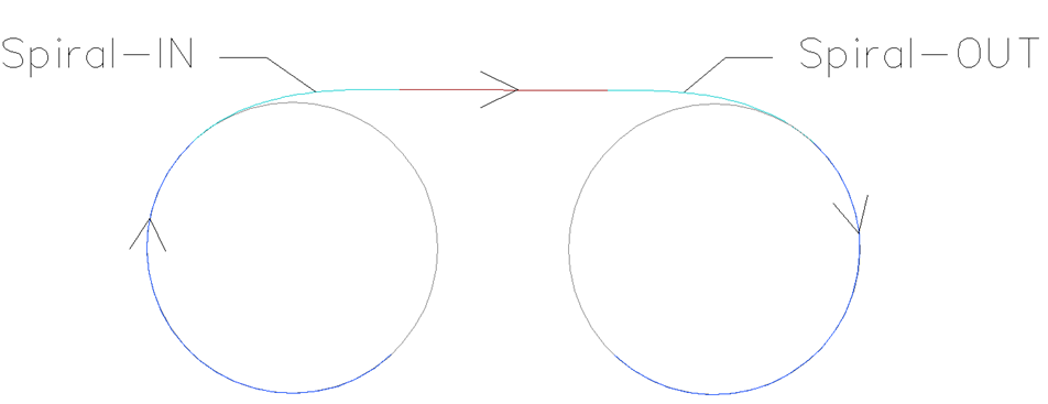
- Spirale-Linea-Spirale
- Crea una nuova combinazione spirale-linea-spirale, con una lunghezza di transizione specificata, tra due elementi di curva esistenti. La nuova combinazione viene disegnata tangenzialmente a entrambi gli elementi di collegamento.Note: La posizione dei punti sugli elementi (di attacco), tra i quali viene creata una nuova combinazione, e i parametri di spirale vengono regolati in base alla modifica degli elementi di attacco.
- Specificare prima / seconda entità
- Consente di selezionare il primo e il secondo elemento di allineamento, tra i quali viene creato un nuovo elemento.
- È angolo soluzione curva
- Alterna tra MAggioredi180 e MInoredi180.La figura seguente mostra due possibili soluzioni per una curva con un angolo < 180° (a sinistra) e > 180° (a destra) aggiunti tra una linea non vincolata e un elemento arco.
- Parametro spirale A
- Consente di specificare il rapporto A1/A2.
- Lunghezza spirale
- Consente di specificare il rapporto L1/L2.
- Spirale in-lunghezza
- Consente di specificare la lunghezza della spirale in entrata.
- Spirale out-lunghezza
- Consente di specificare la lunghezza della spirale in uscita.La figura seguente mostra la combinazione spirale-linea-spirale, creata tra due curve non vincolate, in cui l'utente specifica le lunghezze spirale-IN e spirale-OUT.
- Specificare raggio
- Consente di specificare il raggio del nuovo elemento di transizione e curva.