


AMDATUMID command
Creates a datum identifier symbol

Icon: 
Method
Select the object to attach the datum identifier symbol and specify the points for its location, then the Datum Identifier dialog box opens. The first leader segment is perpendicular to the attached object.
- Hay dos casos de uso para activar las entidades mecánicas:
-
- Al crear un nuevo dibujo que contiene entidades mecánicas:
- Configure la variable del sistema LOADMECHANICAL2D en ON (1).
- Inicie un nuevo plano utilizando una plantilla Mechanical2d.
- Al abrir un dibujo que contiene entidades mecánicas:
- Configure la variable del sistema LOADMECHANICAL2D en ON (1).
- Abra un dibujo ACM existente e inicie la creación de símbolos especiales.
- Al crear un nuevo dibujo que contiene entidades mecánicas:
Note: Estas dimensiones son compatibles con la aplicación AutoCAD® de Mechanical heredada.
Note: El símbolo se añadirá a la capa AM_5.
Note: Después de abrir un plano que contiene entidades mecánicas, llenar otros planos con datos relacionados con la mecánica se realizará a pedido en contraste con las versiones anteriores. Será posible cuando un usuario copie las entidades relacionadas con la mecánica al dibujo de vainilla. En el caso de la copia, las entidades que no están relacionadas con los datos mecánicos, un dibujo de vainilla no se llenará de datos mecánicos.
Note: Al abrir un dibujo que contiene entidades mecánicas, pero la variable de sistema LOADMECHANICAL2D está desactivada, se muestra una burbuja de advertencia en la barra de estado que describe la situación y proporciona un hipervínculo para activar y cargar inmediatamente los módulos mecánicos 2D.
The Datum Identifier dialog box allows you to set all parameters for the symbol.
Symbol
Specifies the datum identifier symbol characteristics.
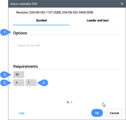
- Options (1)
- Toggles the datum type.
- Identifier (2)
- Defines the identifier which can contain a maximum of two characters.
- Thread note (3)
- Defines the thread notes, which are placed on symbols attached to gears or screw threads. They specify which diameter to use as the datum.
- Datum note (4)
- Defines the reference datum targets which correspond to points on a surface. Generally, it contains a series of datum targets separated by commas (",").
Note: Thread and datum notes are not available for all standards.
Leader and text
Specifies the Leader and text characteristics.
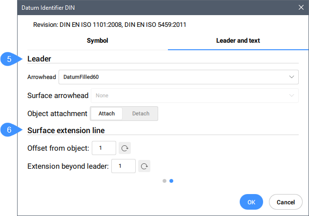
- Leader (5)
- Sets the leader characteristics.
- Arrowhead
- Sets the default leader arrowhead type.
- Surface arrowhead
- Sets the arrowhead for surface indication leaders. Note: This option is only available for the standards which allow surface indicator leaders.
- Object attachment
- Defines if the symbol leader is attached or detached to the object.
- Attach
- Attaches the symbol to the selected object.
- Detach
- Detaches the symbol from the object.
- Surface extension line (6)
- Sets the surface extension line characteristics.
- Offset from object
- Sets the offset from the object.
- Extension beyond leader
- Sets the extension beyond leader.
After creating the datum identifier symbol with the AMDATUMID command, their properties can be changed in the Properties panel:
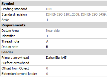
- Symbol
-
- Drafting standard
- Displays the drafting standard.
- Standard revision
- Displays the standard revision.
- Scale
- Sets the note scale.