APPFOT
Posiziona nei disegni i glifi della fotocamera che puntano agli obiettivi e crea viste con nome.

Icona: 
Metodo
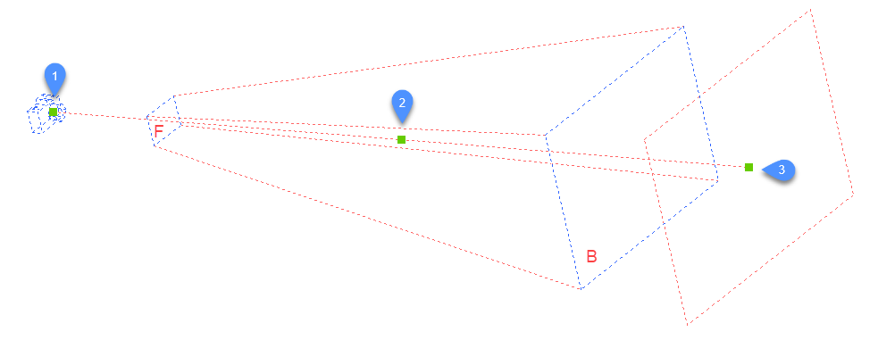
Specificare la posizione della fotocamera e la posizione dell'obiettivo (il punto in cui la telecamera guarda).
Nel disegno viene visualizzato un glifo della fotocamera per indicare la posizione della stessa.
Note: Nel disegno viene visualizzato un glifo della fotocamera per indicare la posizione della stessa.
Opzioni
- ?
- Visualizza l'elenco di fotocamere esistenti. Premere Invio per elencare tutte le fotocamere esistenti.
Utilizzare i caratteri jolly (* o ?) per elencare una selezione di fotocamere. Ad esempio, Cam* elenca tutti i nomi delle telecamere che iniziano con "cam" e ?a* elenca tutti i nomi delle telecamere la cui seconda lettera è "a"
- Nome
- Assegna un nome alla nuova fotocamera.
- Posizione
- Posiziona l'apparecchio fotografico selezionando un punto nel disegno o digitando le coordinate x, y, z nella Barra dei comandi.
- Altezza
- Imposta l'altezza (coordinata z) della fotocamera.
- Obbiettivo
- Posiziona la destinazione, ovvero il punto in cui la fotocamera guarda selezionando un punto nel disegno o digitando le coordinate x, y, z nella Barra dei comandi.
- Distanza focale
- Definisce la lunghezza dell'obiettivo. Un numero più piccolo, ad esempio 20, fornisce un campo visivo più ampio, mentre un numero più alto, ad esempio 200, fornisce uno sguardo più ravvicinato, come un obiettivo zoom su una fotocamera.
- Ritaglio
- Definisce i piani di ritaglio anteriore e posteriore, che tagliano la vista.
- Vista
- Imposta la fotocamera come vista corrente.
-
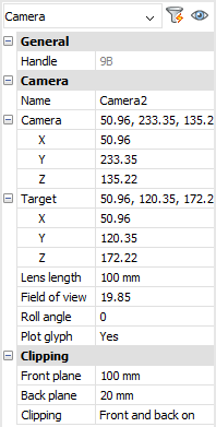
Note: Le proprietà di una vista fotocamera possono essere modificate:
- nella finestra di dialogo visualizzata dal comando VISTA.
- nel pannello Proprietà dopo aver selezionato il glifo della fotocamera nel disegno.
-
- Modifica mediante grip
- Le fotocamere possono essere modificate direttamente tramite i grip:
-