CHAMFER command
Creates chamfers at intersections, defined by two lengths, or a length and an angle.

Icon: 
Alias: CHA
Methods
There are four methods to create chamfers:
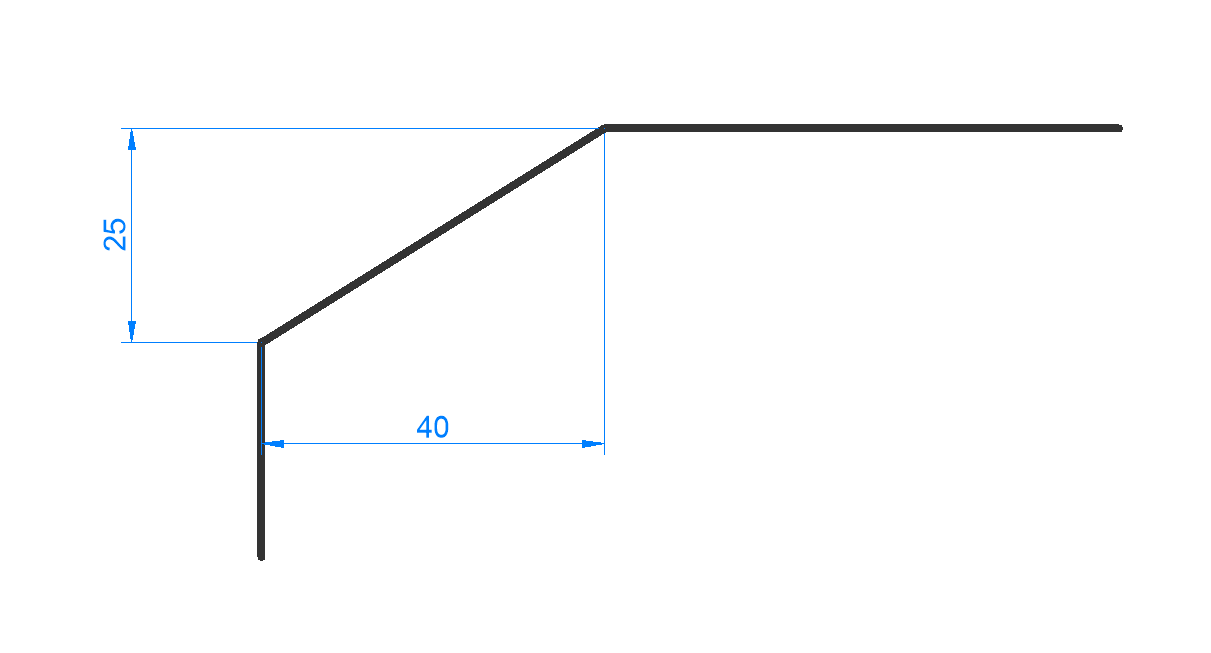
- Create chamfer by specifying two distances.
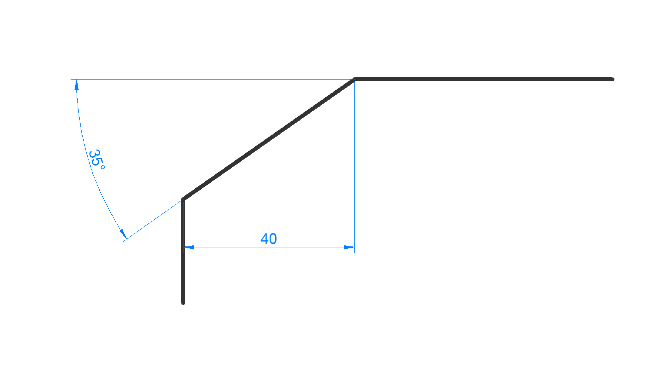
- Create chamfer by length and angle.
- Create chamfers along a polyline.
- Create chamfers on a 3D solid edge (obsolete, replaced by DMCHAMFER command).
Note: The command cannot place a chamfer between two polylines, but it can place a chamfer between a line and a polyline, even a closed polyline.
Note: To connect two entities without creating a chamfer, hold the Shift key when selecting the second entity. This acts like a combined Trim-Extend command.
Options within the command
- chamfer Settings
- Opens the Settings dialog box at the chamfer parameters.
- Polyline
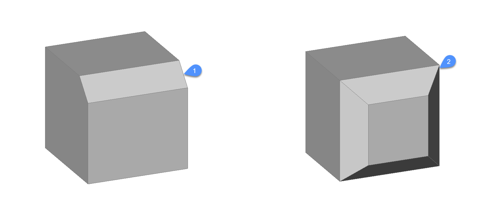
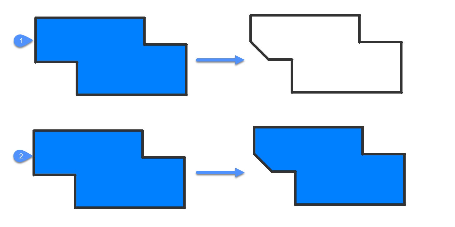
- Chamfers the vertices where two segments meet of the selected polyline (if applicable).Note: Creating chamfers on a hatch boundary created with individual lines (1) results in removal of hatch associativity. Associativity is maintained if the boundary is defined from a polyline (2).
- Angle
- Changes the method to length-angle.Note: BricsCAD measures the angle from 0 degrees, the X axis.
- Distance
- Changes the method to distance-distance.
- mEthod
- Specify between angle and distance methods.Note: The program will keep using the same method for determining the chamfer until the method is changed again.
- Trim
- Determines if the entities are trimmed or extended to meet the endpoints of the chamfer line.
- Undo
- Undoes the last chamfer when in multiple mode.
- Multiple
- Create multiple chamfers with the same settings. Press the Esc key to exit the command.
- Create 3D chamfer
- Create 3D chamfer by selecting the edge of a 3D solid or surface.
- Enter surface selection option
- Select between surfaces adjacent to the selected edge.
- Select edge or Loop
- Select edge (1) to be chamfered or loop around selecting all tangential edges belonging to the base surface (2).