


Comando DMDEFORMAPUNTO
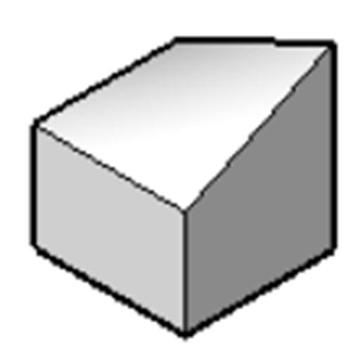
Deforma una regione, una o più facce di un solido 3D o di una superficie spostando un punto che giace su una di esse in direzione 3D arbitraria.

Icona: 
Descrizione
Deforma una regione, una o più facce collegate di un solido 3D o di una superficie spostando un punto che giace su una di esse in una direzione 3D arbitraria. Le facce selezionate vengono deformate nel modo più fluido possibile. La continuità iniziale tra le facce deformate (G1 – facce tangenti, o G2 – continuità di curvatura) viene mantenuta quando deformato.
Selezionare una regione o una faccia o alcune facce connesse di un solido o di una superficie 3D, quindi specificare il punto di deformazione e il valore di deformazione per deformare l'entità.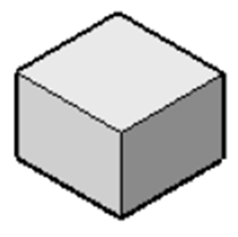
Opzioni
- cambia Parametri
- Scegliere un metodo per modificare i parametri.
- Alfa
-
Specificare la resistenza allo stiramento. È un tensore del secondo ordine che può essere descritto con tre numeri. Ogni valore deve essere 0 o un numero positivo:
- alfa U: resistenza in direzione U,
- alfa V: resistenza in direzione V,
- alpha theta: l'angolo tra le direzioni principali U e V della superficie e le direzioni delle proprietà del materiale.
- Beta
- Specificare la resistenza alla piegatura. Analogamente all'Alfa, Beta è definita come una tripla: beta U, beta V, beta theta. Ogni valore deve essere 0 o un numero positivo.
- Gamma
- Specifica la resistenza alla velocità di variazione della piegatura. Il valore deve essere 0 o un numero positivo.
- Delta
- Specifica la resistenza alle deviazioni dalla forma predefinita. Il valore deve essere 0 o un numero positivo.
- impostare il punto di Destinazione
- Le entità vengono deformate verso il punto specificato.
- imposta DIrezione
- Le entità selezionate vengono deformate dinamicamente nella direzione specificata.
- cambia punto Base
- Selezionare un nuovo punto di deformazione.