


MATERIALS command
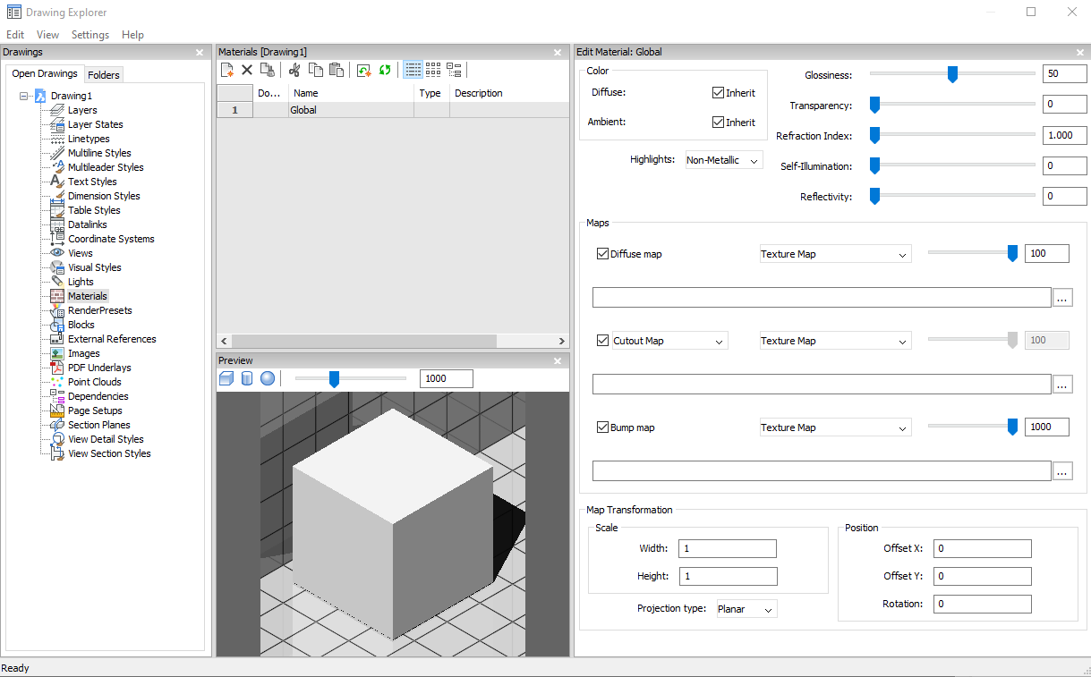
Opens the Drawing explorer dialog box with Materials selected.

Icon: 
Alias: FINISH, MAT, RMAT
Method
Open the Drawing explorer dialog box with Materials category selected to view and modify Materials in the current drawing.
Options within the command
- Preview options
- Cube
- Displays a preview of the selected material applied to a cube.
- Cylinder
- Displays a preview of the selected material applied to a cylinder.
- Sphere
- Displays a preview of the selected material applied to a sphere.
- Light Intensity
- Sets the light intensity in the Preview window.
- Color
- Diffuse
- Sets the diffuse color. You can click the colored tile to choose a color in the Select Color dialog box. When Inherit is checked on, the entity color is applied.
- Ambient
- Sets the ambient color. You can click the colored tile to choose a color in the Select Color dialog box. When Inherit is checked on, the entity color is applied.
- Highlights
- Sets the highlight property of the material. You can choose between Non-metallic or Metallic.
- Glossiness
- Defines the glossiness of the material surface. You can choose a number in the range of 0 – 100.
- Transparency
- Defines the transparency of the material surface. You can choose a number in the range of 0 – 100.
- Refraction Index
- Defines the refraction index of the material surface. You can choose a number in the range of 1.00 – 3.00.
- Self-Illumination
- Defines the self-illumination of the material surface. You can choose a number in the range of 0 – 100.
- Reflectivity
- Defines the reflectivity of the material surface. You can choose a number in the range of 0 – 100.
- Maps
-
Texture maps add detail to a surface, which is not included in the 3D model itself.
Note: The TextureMapPath user preference defines the search path for texture map images. In the BricsCAD program folder exist three subfolders under Textures, each containing a number of texture files of the same name. Images in folder 1 have a size of 256 x 256 pixels, folder 2 contains images of 512 x 512 pixels, images in folder 3 have a size of 1024 x 1024 pixels. If the Diffuse map setting of a material uses the image name only (not path), you can control the quality of a rendered image by setting the TextureMapPath user preference to folder 1 , 2 or 3.
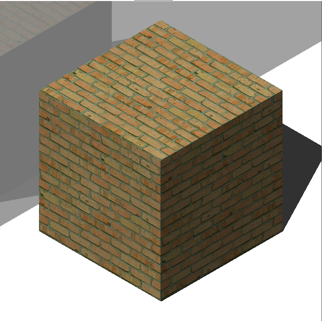
- Diffuse map
- Diffuse maps apply a texture to the surface of a material such as wood grains,
bricks, or tiles. You can select a texture bitmap file with the Browse button.
The selected Texture Map can be applied as Transparency Map or as Cutout
Map.
- Blend factor
- Sets the intensity of the texture map. In this way you can blend the texture map with the Color settings. You can set the blend factor in a range of 0 to 100.
- Transparency Map
-
If Transparency Map is selected, the selected Texture Map image defines a transparency map. The image is recommended to be a grayscale image. White pixels will be invisible, black pixels will be opaque and gray pixels will be transparent.
Note: If you select a colored image, it will be converted to a grayscale image in the background. The alpha channel of the image is ignored.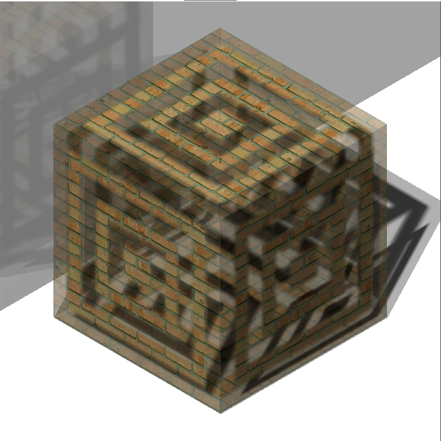
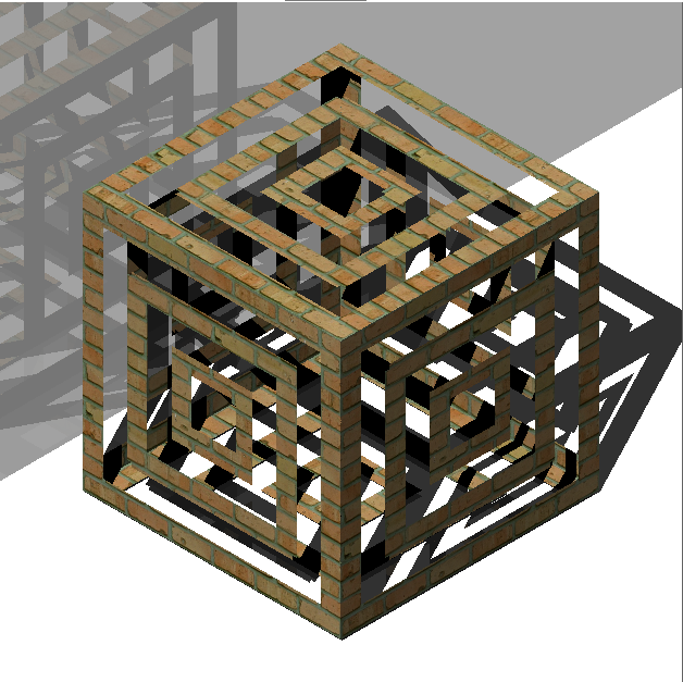
- Cutout Map
- If Cutout Map is selected, then the selected transparency map defines cutouts.
White pixels are visible, and black pixels are invisible. The image is
recommended to be a bitonal black-and-white image, without grays.
- Cutout Map Inverted
-
Inverts the Cutout Map effect. Black pixels are visible and white pixels are invisible.
 Note: If you select a colored or grayscale image, it will be converted to a black-and-white image in the background. The alpha channel of the image is ignored.
- Blend factor
-
The transparency values in the texture will approach the scalar Transparency setting as the blend factor approaches 0. This means that if the Blend factor is 100, then the transparency value will be controlled completely by the Texture Map image. If the Blend factor is 0, the transparency texture will be completely ignored and the scalar Transparency value will be used.
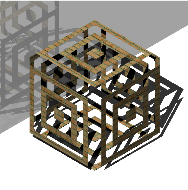
Bump map
Simulates bumps and wrinkles on the surface of an object. The result is a bumpy surface although the surface of the underlying object is not modified.
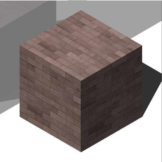
Left: Diffuse map only, Right: Bump Map applied
- Blend factor
- Defines the amount of bump which is applied to the material.
- Map Transformation
- Scale
- The texture map image is applied at a size of 1 drawing unit multiplied by the Width and Height factors. E.g. if the Width and Height factors or both set to 10, the size of the texture image is 10 x 10 drawing units.
- Position
- Offset
-
Texture maps are tiled starting from the origin of the WCS.
To adjust the tiling, you can define an Offset X and Offset Y. The offsets are expressed in drawing units.
- Rotation
- Sets the rotation of the texture maps.
- Projection type
- Defines the way the material is projected onto the object.
Context menu options
- New
- Creates a new material.
- Delete
-
Deletes material definitions from the drawing. The following material definition cannot be deleted:
- Global
- Materials in use
- Rename
-
Renames the material.
Note: Following material cannot be renamed: Global.
- Select All
- Selects all material definitions.
- Invert selection
- Deselects the current selection and vice versa.
- Convert to regular material
- Converts materials to regular material and makes it possible to edit them.
- Add material(s) to library
- Adds materials to the material library so you can use them in other files as well.