


OPTIMIZE command
Corrects inaccuracies in the drawing, for 2D entities or 3D entities.

Icon: 
Description
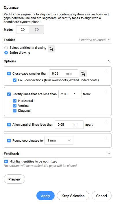
This command works with either 2D entities or 3D entities. The supported 2D entities are lines, arcs and polylines. The command makes corrections such as small gaps between lines or near vertical, horizontal and diagonal lines.
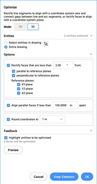
The supported 3D entities are solids, 3D regions and surfaces. The command makes corrections such as faces that are near parallel to the orthogonal planes to be coplanar to these planes; and faces that belong to different solids to be coplanar to one another.
This command opens the Optimize command context panel.
- The options within the OPTIMIZE command are the same as in the Optimize command context panel.
- The Optimize command context panel allows you to toggle On/Off the live Feedback. When turned On, it highlights the entities that match the selected options and displays the number of entities that will be optimized.
Methods
There are two methods to begin optimizing entities:
- Entire drawing
- When this option is selected, all non-frozen entities in the current viewport are used as input.
- selection options (?)
- Allows to choose a selection method. See the SELECT command.
Options within the command, in 2D mode
- change reference Angles
- This option determines which entities will be optimized based on their orientation.Note: In the Optimize command context panel set the value for the Rectify lines that are less than option.
- Horizontal lines
- Corrects near horizontal lines according to the angle tolerance.
- Vertical lines
- Corrects near vertical lines according to the angle tolerance.
- 45-Degree lines
- Corrects near 45° lines according to the angle tolerance.
- All
- Corrects near horizontal, near vertical and near 45° lines according to the angle tolerance.
- None
- Does not correct entities based on their orientation.
- change Tolerances
- Allows you to set the tolerances for the parameters used during the optimization.
- Angle tolerance
- Sets the angle tolerance in degrees, with respect to the World Coordinate System (WCS). Near horizontal, vertical or diagonal lines within this angle tolerance will be optimized.Note: In the Optimize command context panel set the value for the Rectify lines that are less than option.
- Distance tolerance
- Sets the distance tolerance (see Note). Parallel lines within this distance will be merged.Note: In the Optimize command context panel set the value for the Align parallel lines less than option.
- Rounding precisions
- Sets the rounding precision (see Note). This option rounds the coordinates to the specified number of digits following the decimal.
- Gap tolerance
- Sets the gap tolerance (see Note). Gaps between collinear lines within the gap tolerance will be filled.Note: In the Optimize command context panel set the value for the Close gaps smaller than option. Gaps smaller than this value will be closed with a transparent red circles in the drawing. You can also use the picker (
 ) to set the gap tolerance by specifying two points in the drawing.
When the Fix T-connections (trim overshoots, extend undershoots) option is check, the lines are trimmed and extended to close T-connections for smaller gaps than gap tolerance value.
- change Options
- Determines if gaps will be closed, if the lines will be aligned with a referenced direction, and if the drawing will be rounded.
- close Gaps
- If this option is enabled, the gaps between collinear lines that are smaller than the gap tolerance will be closed.Note: In the Optimize command context panel tick the Close gaps smaller than checkbox.
- rectify Lines
- If this option is enabled, entities will be aligned along the referenced directions (horizontal, vertical or diagonal) when their deviation are less than the specified angle tolerance.Note: In the Optimize command context panel tick the Rectify lines that are less than checkbox.Note: If this option is disabled, the Round Coordinates option will be disabled too.
- Make lines Collinear
- If this option is enabled, lines that are almost collinear will be aligned as collinear.
- Round coordinates
- If this option is enabled, it rounds the coordinates to the rounding precision.
If this option is disabled, the drawing will not be rounded.
Note: In the Optimize command context panel tick the Round coordinates to checkbox.Note: This action is controlled by the Rounding precision tolerance setting.
- enable All
- Enables all close Gaps, Make lines Collinear, and Round coordinates options.
- change Input selection
- Allows you to make a new selection of entities to be used by the command.
- apply settings and PReview
- Makes a preview of the rectified segments. You can accept or reset the result.
- Keep selection
- Clicking this button will cancel the command without optimizing, but with keeping the highlighted lines selected. This option allows you to select suboptimal lines in a drawing.
- switch to 3d Mode
- Switches the mode to 3D.
Options within the command, in 3D mode
- change reference Plane
- Determines which plane will be the referenced for correcting faces position. You can choose XY plane, YZ plane, XZ plane or all of them.
- change Tolerances
- This option allows setting the tolerances for the parameters used during the optimization.
- Angle tolerance
- Sets the angle tolerance, in degrees, for a relative position of faces and planes.Note: In the Optimize command context panel set the value for the Rectify faces that are less than option.
- Distance tolerance
- Sets the distance tolerance (see Note).The faces within the tolerance will be made coplanar, parallel or perpendicular, according to the settings.Note: In the Optimize command context panel set the value for the Align parallel faces if less than option.
- Rounding precisions
- Sets the rounding precision (see Note). This option rounds the coordinates to the specified number of digits following the decimal.Note: In the Optimize command context panel set the value for the Round coordinates to option.
- change Options
- Changes the options for correcting the faces position.
- make faces Coplanar
- Makes the faces in the selection coplanar, with respect to the values in the Tolerances section.
- rectify faces PArallel to reference planes
- Makes the faces in the selection parallel to the selected reference planes, with respect to the values in the Tolerances section.
- rectify faces PErpendicular to reference planes
- Makes the faces in the selection perpendicular to the selected reference planes, with respect to the values in the Tolerances section.
- Round coordinates
- If this option is enabled, it rounds the coordinates to the rounding precision.
If this option is disabled, the drawing will not be rounded.
Note: This action is controlled by the Rounding precision setting.
- enable All
- All the options for 3D faces (coplanar, parallel, perpendicular and round) will be used by the command.
- change Input selection
- Allows making a new selection of entities to be used by the command.
- apply settings and PReview
- Makes a preview of the rectified faces. You can accept or reset the result.
- Keep selection
- Clicking this button will cancel the command without optimizing, but with keeping the highlighted entities selected. This option allows you to select suboptimal entities in a drawing.
- switch to 2d Mode
- Switches the mode to 2D.