PARAMETRICSTRETCH command
This command defines a parameter to be used by a stretch operation on some entities of a parametric block.

Icon: 
Methods
This command allows to stretch some entities in a block. The appearance of the block can be controlled by changing the value of the parameter associated with the stretch operation.
The goal of this parametric stretch action is to simplify the stretching of entities in the block. Usually, the same behavior could be obtained with parameters and constraints, but it would take more time and effort to obtain the same behavior.
The PARAMETRICSTRETCH command can be launched from the command line by typing _PARAMETRICSTRETCH. Another way to launch this command is from the ribbon in a Drafting workspace. Go to tab .
Options within the command
- Base point of displacement
- A location point for the origin of the stretch vector.
- Second point of displacement
-
A location point for the head of the stretch vector.
For example, when defining a parametric block for a bed symbol, the stretch vector could look like this: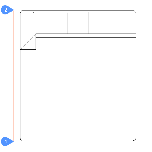
The point marked with 1 is the base point of displacement (the origin of the vector) and the point marked with 2 is the second point of displacement (the head of the vector). The two points are located on a vertical line at a distance equal to the length of the bed. The points can be placed on the actual geometry if this is more convenient for the user. Here, for visualization purposes, the points have been placed on the side of the block.
The parametric stretch vector will have a soft red color and will be placed on a special layer named PARAMETRIC_STRETCH_VECTORS.
- Construct stretch frame: pick first point of rectangular frame [Polygonal]
- The first corner of the rectangular stretch frame.
- Opposite corner
- The second corner of the rectangular stretch frame .
- Polygonal
-
Allows to enter a series of points that will set a polygonal stretch frame.
Note: The vertices inside the selection contour (rectangle or polygon) will be moved according to the stretch vector.
- Select/deselect entities which can be affected by the stretch [selection options (?)]:
-
Allows to edit the selection of entities to be affected by the stretch action.
By default, all the entities which have stretch points inside the stretch frame are selected. Using this option, the user can change the selection. All the selected entities will be highlighted.
At this step, the screen will look like this: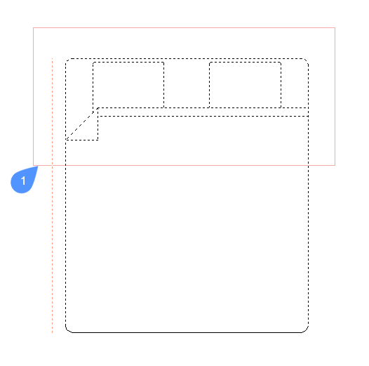
The contour marked with 1 is the stretch frame. The vertices that are inside this contour and belong to a selected entity, will be affected by the parametric stretch.
- Enter name for the stretch parameter <Stretch>:
-
Allows to give a name to the stretch parameter. The default name is Stretch.
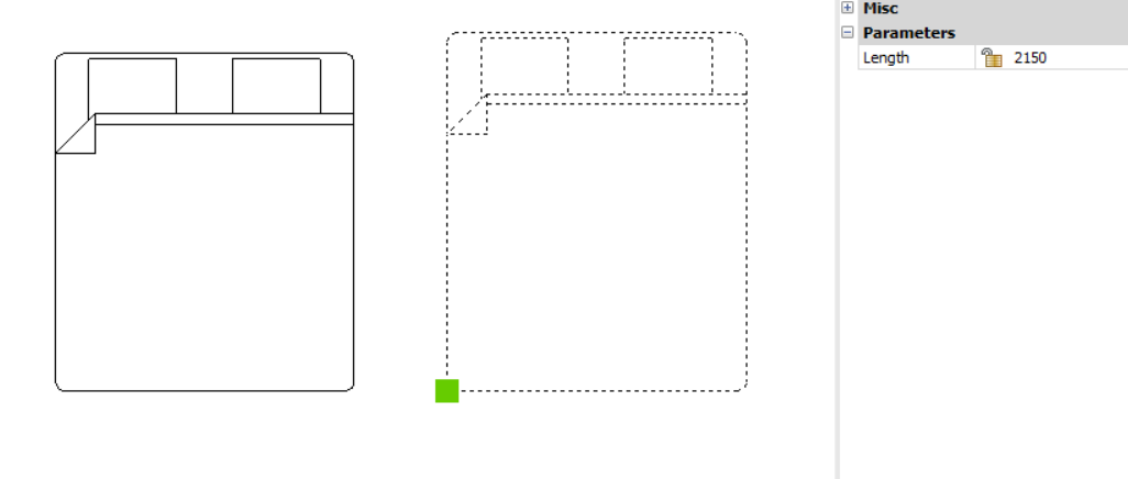
For this example, the stretch parameter is named Length.
To see the block at work, open a new drawing and insert the block. After insertion, with the block selected, go to the Properties panel in the Parameters section, and change the value of the stretch parameter, Length in this case.
The block entities that were selected for stretch will adjust according to the new value of the stretch parameter.