


SECTIONPLANESETTINGS command

Icon: 
Description
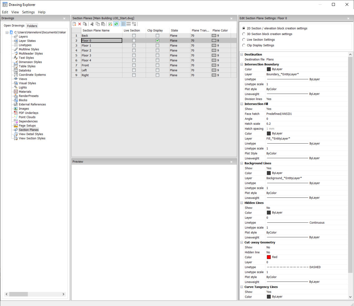
Opens the Drawing Explorer dialog box with Section Planes category selected.
Methods
Open the Drawing explorer dialog box with Section Planes category selected to view and modify section planes in the current drawing.
Options within the command
- Section Types
-
- 2D Section/elevation block creation settings
- Specifies properties for 2D sections and elevations. These
properties are assigned to the 2D section you create as a
block.
- 3D section block creation settings
- Specifies properties for 3D sections. These properties are
assigned to the 3D section you create as a block.
- Live Section Settings
- Specifies properties for live sections. With live sections, the
entities in the drawing are temporarily modified and viewable in
the drawing.
- Clip Display Settings
- When using the clip display status, the display of entities is
clipped. The status can be set for multiple section entities
simultaneously.
- Destination
-
- Destination file
- Specifies the destination file to save the section plane to.
- Intersection Boundary
-
- Color
- Defines the color of the intersection boundary. You can choose a color from the drop list or choose Select Color, the Select Color dialog box will then display.
- Layer
-
Specifies the layer of the intersection boundary. You can choose between:
-
The available layers in the drawing.
-
*EntityLayer*_IntersectionBoundary: the properties of layers of the entities in the section are kept, but a copy of these layers is created.
Note: This overwrites the other specified properties. -
New layer name settings: option opens the New Layer Name dialog box. Here you can edit the name settings for the option above.
-
- Linetype
-
Specifies the linetype of the intersection boundary. You can choose between:
- The available linetypes in the drawing
- Load to load new linetypes. This opens the Load Linetypes dialog box where you can choose new linetypes to load into the drawing.
- Linetype scale
- Specifies the linetype scale of the intersection boundary.
- Plot style
- Specifies the plotstyle of the intersection boundary.
- Lineweight
- Specifies the lineweight of the intersection boundary.
- Division lines (option available for the 2D sections)
- Specifies whether the division lines of the intersection boundary should be drawn.
- Show (option available for the 3D sections)
-
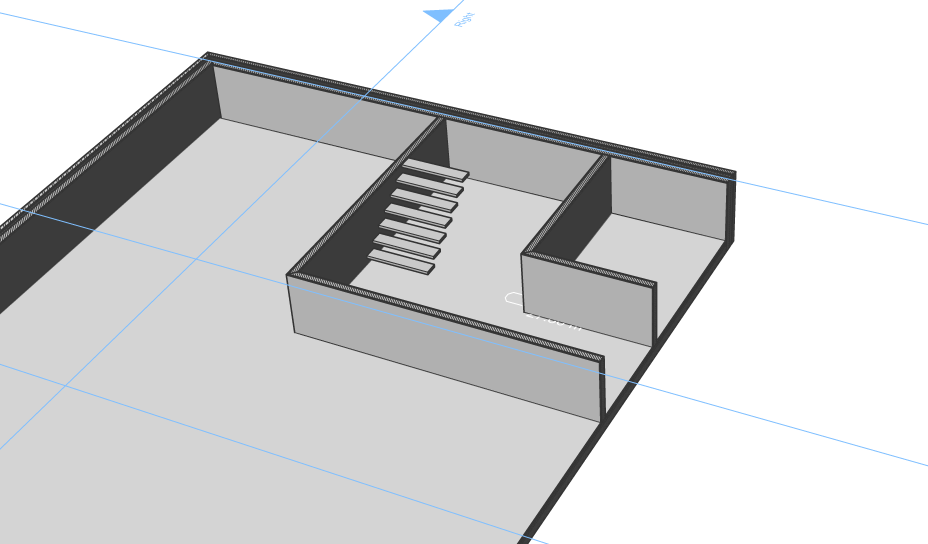
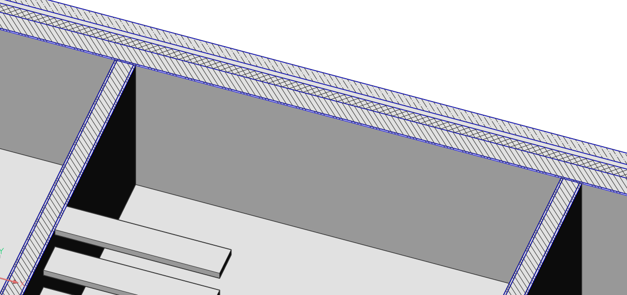
Specifies whether the intersection boundary is drawn.
- Yes: the intersection boundary is displayed. The
intersection boundaries are indicated in blue.
- No: no intersection boundary is displayed.
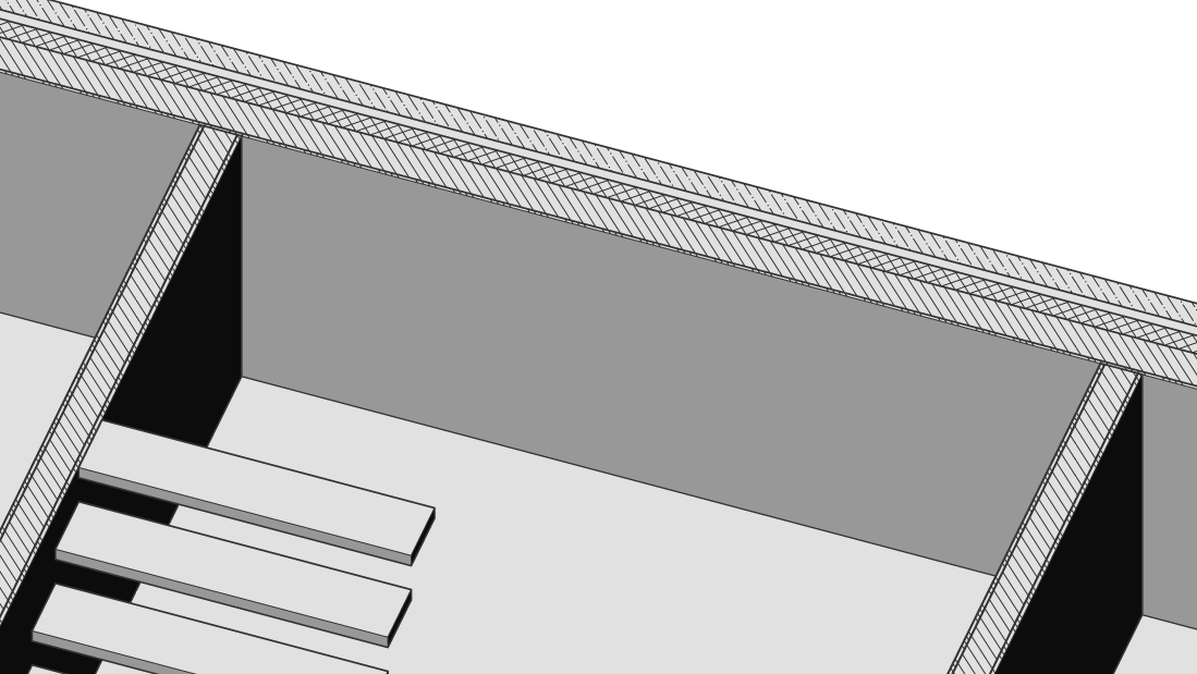 Note: The intersection boundary is still visible, since the lines are also drawn for the intersection fill. The color is now determined by the intersection fill instead of by the intersection boundary.
- Yes: the intersection boundary is displayed. The
intersection boundaries are indicated in blue.
- Intersection Fill
-
- Show
-
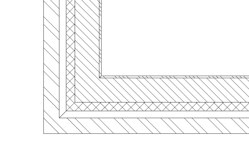
Specifies whether the intersection filling is showed.
-
Yes: the cut through geometry is displayed by a hatch
-
No: no hatch is drawn on the cut through geometry
-
- Face hatch
- Specifies the used hatch pattern to fill the section. Opens the Hatch Pattern Type dialog box where you can choose a hatch pattern.
- Angle
- Specifies the angle of the hatch pattern.
- Hatch scale
- Specifies the scale of the hatch pattern.
- Hatch spacing
- Specifies the hatch spacing.
- Color
- Specifies the color of the hatch. You can choose a color from the drop list or choose Select Color, the Select Color dialog box will then display.
- Layer
-
Specifies the layer of the intersection boundary. You can choose between:
-
The available layers in the drawing.
-
*EntityLayer*_IntersectionBoundary: the properties of layers of the entities in the section are kept, but a copy of these layers is created.
Note: This overwrites the other specified properties. -
New layer name settings: option opens the New Layer Name dialog box. Here you can edit the name settings for the option above.
-
- Linetype
-
Specifies the linetype of the intersection boundary. You can choose between:
- The available linetypes in the drawing
- Load to load new linetypes. This opens the Load Linetypes dialog box where you can choose new linetypes to load into the drawing.
- Linetype scale
- Specifies the linetype scale of the hatch pattern.
- Plot Style
- Specifies the plot style of the hatch pattern.
- Lineweight
- Specifies the lineweight of the hatch pattern.
- Background Lines
-
- Show
-
Specifies whether the background lines are drawn. These are the lines that show the geometry behind the section plane, which is not cut-through.
- Yes: the background lines are displayed
- No: no background lines are displayed
- Yes: the background lines are displayed
- Color
- Specifies the color of the background lines. You can choose a color from the drop list or choose Select Color, the Select Color dialog box will then display.
- Layer
-
Specifies the layer of the background lines. You can choose between:
-
The available layers in the drawing.
-
*EntityLayer*_IntersectionBoundary: the properties of layers of the entities in the section are kept, but a copy of these layers is created.
Note: This overwrites the other specified properties. -
New layer name settings: option opens the New Layer Name dialog box. Here you can edit the name settings for the option above.
-
- Linetype
-
Specifies the linetype of the background lines. You can choose between:
- The available linetypes in the drawing
- Load to load new linetypes. This opens the Load Linetypes dialog box where you can choose new linetypes to load into the drawing.
- Linetype scale
- Specifies the linetype scale of the background lines.
- Plot Style
- Specifies the plot style of the background lines.
- Lineweight
- Specifies the lineweight of the background lines.
- Hidden lines
- Show
-
Specifies whether the hidden lines are drawn.
- Yes: the hidden lines are displayed.
- No: no hidden lines are displayed.
- Yes: the hidden lines are displayed.
- Color
- Specifies the color of the hidden lines. You can choose a color from the drop list or choose Select Color, the Select Color dialog box will then display.
- Layer
-
Specifies the layer of the hidden lines. You can choose between:
-
The available layers in the drawing.
-
*EntityLayer*_IntersectionBoundary: the properties of layers of the entities in the section are kept, but a copy of these layers is created.
Note: This overwrites the other specified properties. -
New layer name settings: option opens the New Layer Name dialog box. Here you can edit the name settings for the option above.
-
- Linetype
-
Specifies the linetype of the hidden lines. You can choose between:
- The available linetypes in the drawing
- Load to load new linetypes. This opens the Load Linetypes dialog box where you can choose new linetypes to load into the drawing.
- Linetype scale
- Specifies the linetype scale of the hidden lines.
- Plot Style
- Specifies the plot style of the hidden lines.
- Lineweight
- Specifies the lineweight of the hidden lines.
- Cut-away Geometry
-
- Show
-
Specifies whether the section lines of the geometry that is cut away are shown.
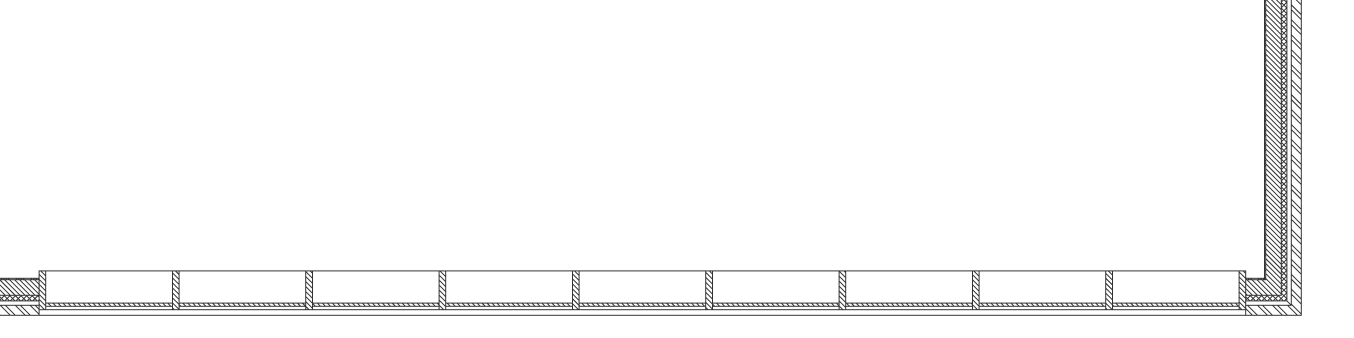
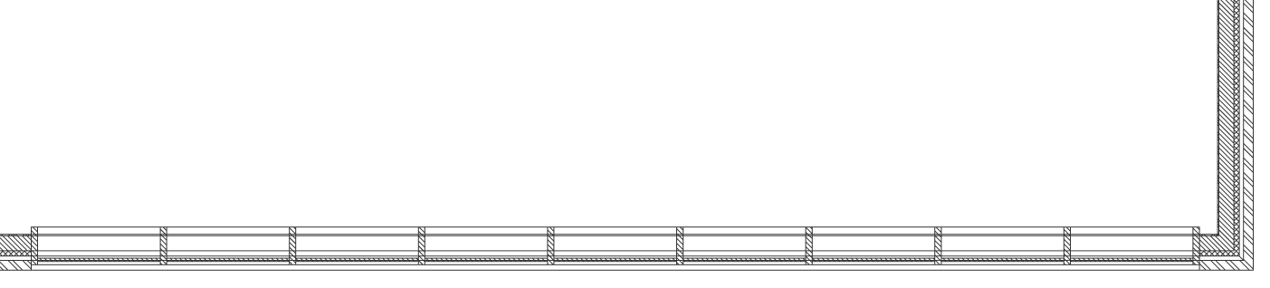
- Yes: the cut-away geometry is displayed.
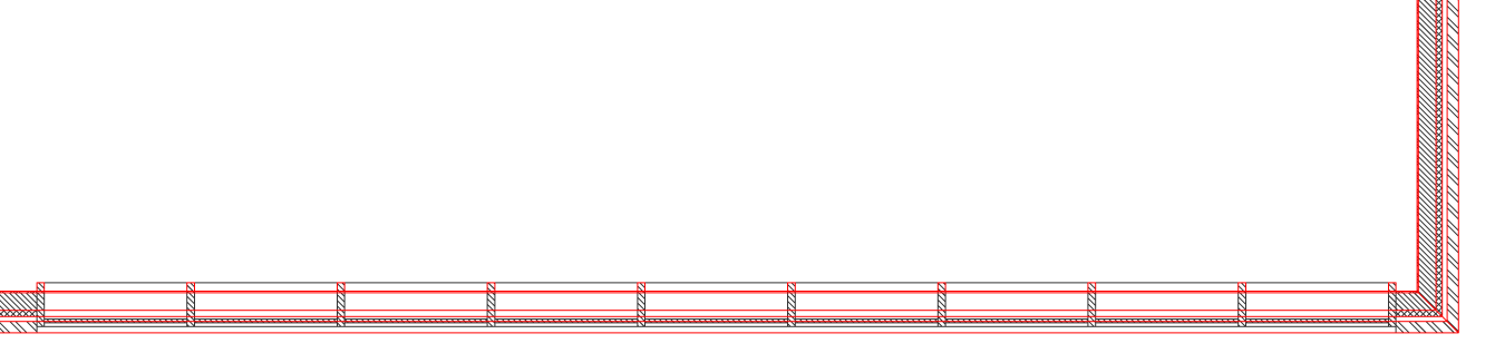
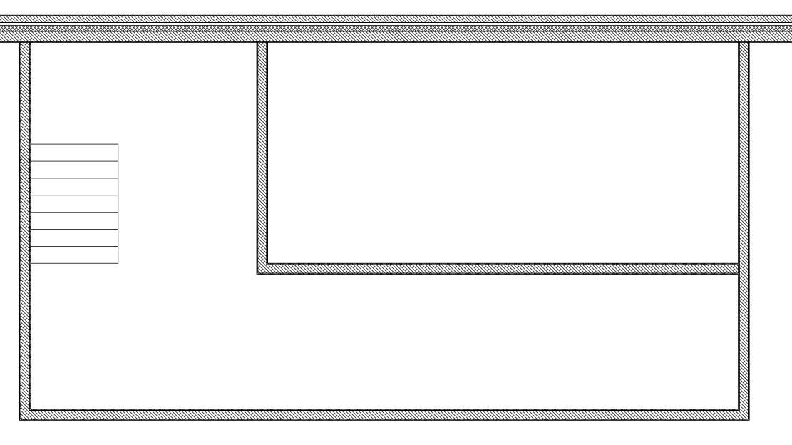
Cut-away geometry of a 2D section.
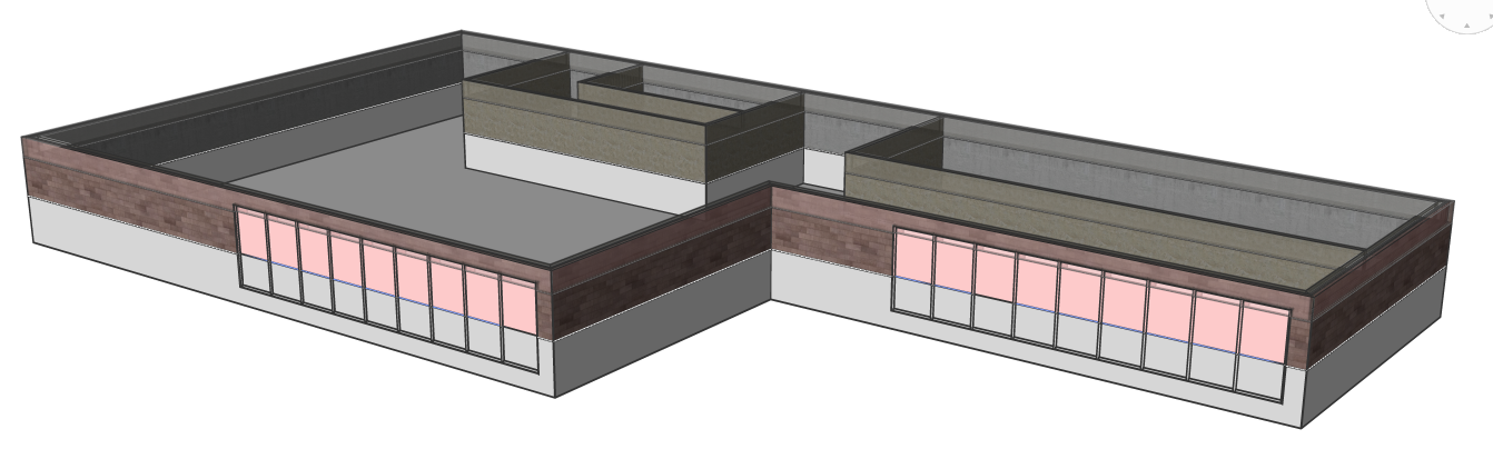
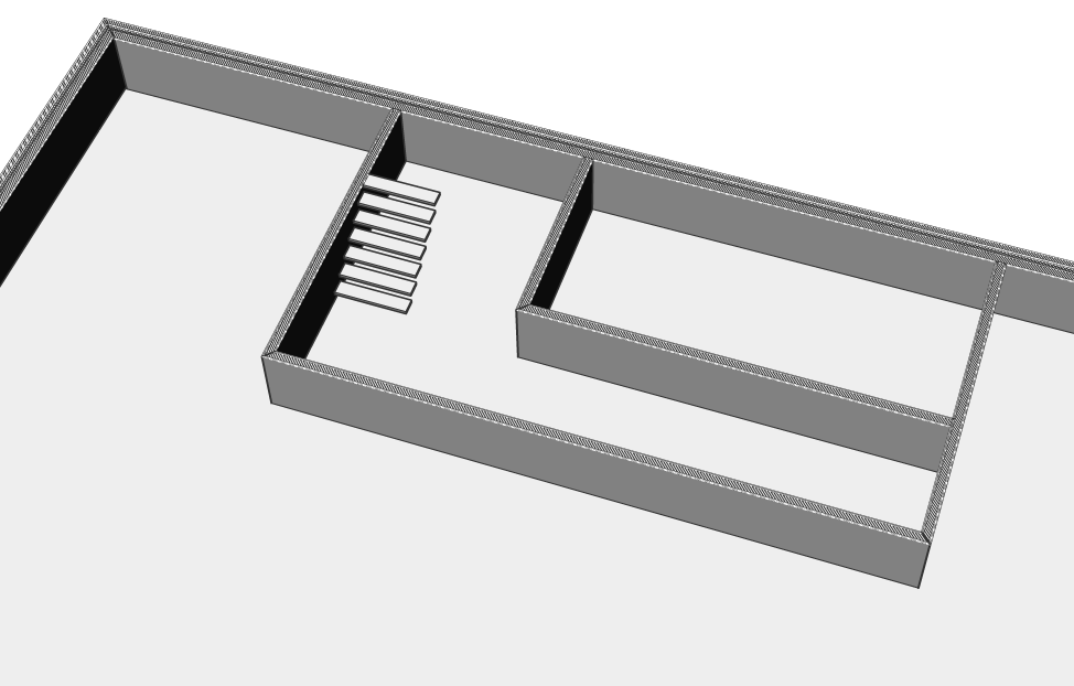
Cut-away geometry of a 3D section.
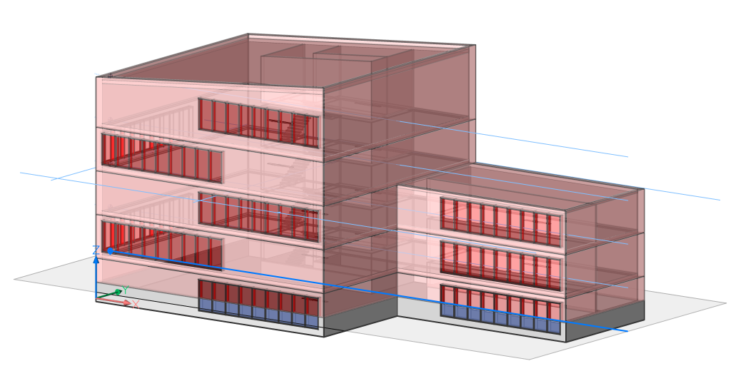
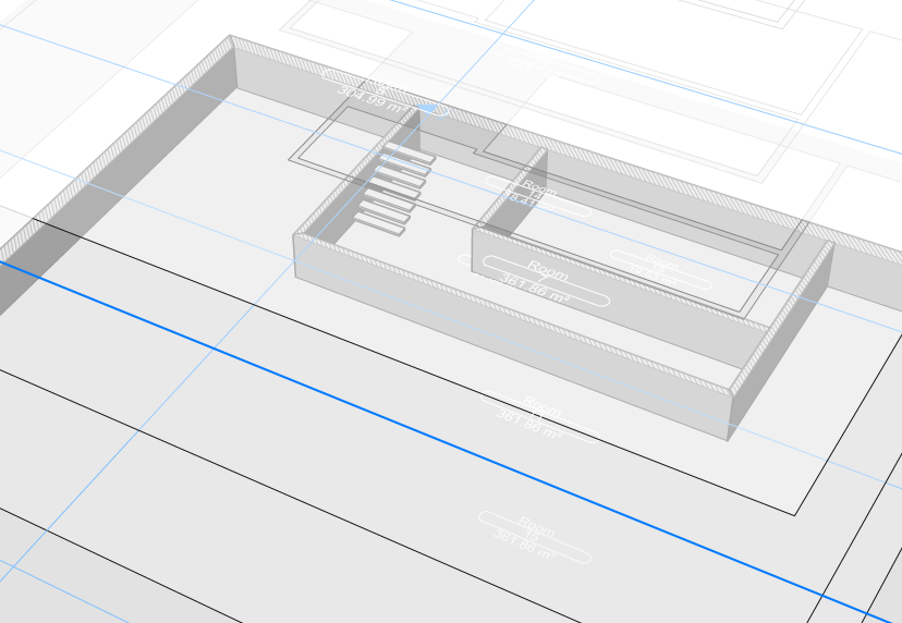
Cut-away geometry of a live section.
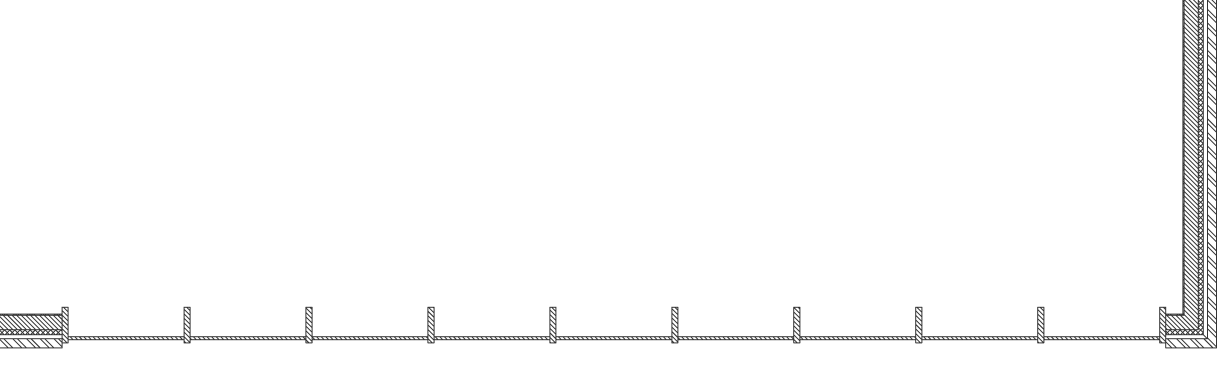
- No: no cut-away geometry lines are displayed
No cut-away geometry of a 2D section is shown.
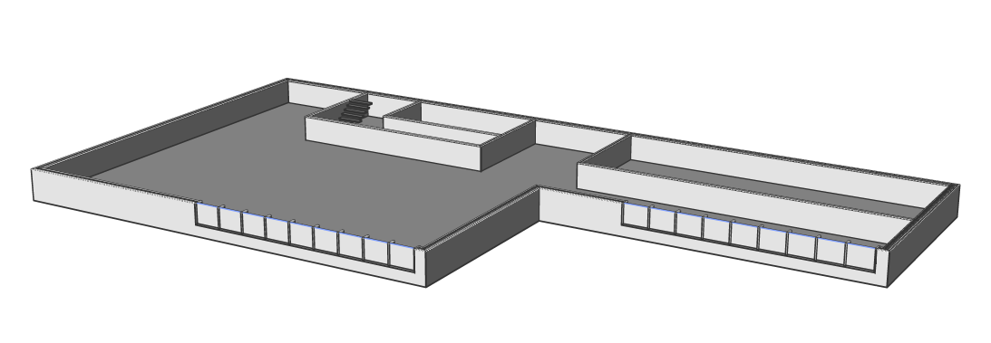
No cut-away geometry of a 3D section is shown.
No cut-away geometry of a live section is shown.
- Yes: the cut-away geometry is displayed.
- Hidden line
- Specifies whether the hidden lines of the cut-away geometry are shown.
- Color
- Specifies the color of the cut-away geometry (lines). You can choose a color from the drop list or choose Select Color, the Select Color dialog box will then display.
- Layer
-
Specifies the layer of the cut-away geometry. You can choose between:
-
The available layers in the drawing.
-
*EntityLayer*_IntersectionBoundary: the properties of layers of the entities in the section are kept, but a copy of these layers is created.
Note: This overwrites the other specified properties. -
New layer name settings: option opens the New Layer Name dialog box. Here you can edit the name settings for the option above.
-
- Linetype
-
Specifies the linetype of the cut-away geometry. You can choose between:
- The available linetypes in the drawing
- Load to load new linetypes. This opens the Load Linetypes dialog box where you can choose new linetypes to load into the drawing.
- Linetype scale
- Specifies the linetype scale of the cut-away geometry lines.
- Plot Style
- Specifies the plot style of the cut-away geometry lines.
- Lineweight
- Specifies the lineweight of the cut-away geometry lines.
- Curve Tangency Lines
-
- Show
- Specifies whether the curve tangency lines are drawn.
- Color
- Specifies the color of the curve tangency lines. You can choose a color from the drop list or choose Select Color, the Select Color dialog box will then display.
- Layer
-
Specifies the layer of the curve tangency lines. You can choose between:
-
The available layers in the drawing.
-
*EntityLayer*_IntersectionBoundary: the properties of layers of the entities in the section are kept, but a copy of these layers is created.
Note: This overwrites the other specified properties. -
New layer name settings: option opens the New Layer Name dialog box. Here you can edit the name settings for the option above.
-
- Linetype
-
Specifies the linetype of the curve tangency lines. You can choose between:
- The available linetypes in the drawing
- Load to load new linetypes. This opens the Load Linetypes dialog box where you can choose new linetypes to load into the drawing.
- Linetype scale
- Specifies the linetype scale of the curve tangency lines.
- Plot Style
- Specifies the plot style of the curve tangency lines.
- Lineweight
- Specifies the lineweight of the curve tangency lines.
Context Menu Options
- New
- Creates a new section plane definitions into the drawing. For a detailed explanation, see the SECTIONPLANE command.
- Delete
- Deletes section planes from the drawing.
- Rename
- Renames the selected section plane.
- Select All
- Selects all section plane definitions.
- Invert selection
- Deselects the current selection and vice versa.