Define Attribute dialog box
Opens via: ATTDEF command
The Define Attribute dialog box defines the options for the attribute values.
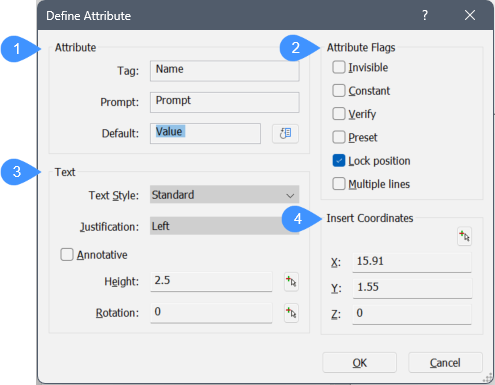
- Attribute options
- Attribute Flags options
- Text options
- Insert Coordinates options
Attribute options
- Tag
Specify the name of the attribute. This is the name by which BricsCAD identifies the attribute. You can use up to 255 letters, numbers and punctuation.
- Prompt
Specify the user prompt. This is displayed at the command prompt when the attribute is later inserted in the drawing. You can leave this field blank. BricsCAD then uses the tag as the prompt during attribute insertion.
- Default
Specify the default value. This is displayed in angle brackets, for example <360>. Press Enter to accept the value.
Click the Insert Field icon to assign a field value to the attribute (see the FIELD command).
Attribute Flags options
- Invisible
Hide the attribute from view; they are not displayed and not printed. However, hidden attributes can be displayed with the ATTDISP command.
- Constant
Specify a default value that cannot be changed.
- Verify
Forces to enter the value a second time. This helps to ensure that the value is entered correctly.
- Preset
Inserts attributes without prompting. The attributes can be changed later with the ATTEDIT command.
- Lock position
- On: locks the position of the attribute within the block reference (default option).
- Off: unlocked attributes can be moved relative to the rest of the block using grip editing.
- Multiple lines
- On: allows the use of multiline text.
- Off: limits to a single line.
When the Multiple lines box is checked, the button icon displays next to the dimmed Default text field.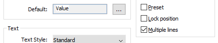
When you click the button, the Define Attribute dialog box temporarily closes to let you define a multiline text entity.
The MTEXT command launches. Type the text for the attribute, then click the OK button on the Text Formatting toolbar to return to the Define Attribute dialog box.
Text options
- Text style
Specify the text style for the attribute text. Choose from one of the styles defined in the drawing. (You can create additional text styles with the STYLE command.)
- Justification
Specify the justification of the attribute text, such as Center or Fit.
- Height
Specify the height of the attribute text, unless overridden by the text style. Enter a value, or specify two points in the drawing by clicking the button. The last option dismisses the dialog box temporarily.
- Rotation
Specify the rotation angle of the rotation text. Enter a value, or specify two points in the drawing by clicking the button. The last option dismisses the dialog box temporarily.
- AnnotativeSpecify the Annotative property of the attribute text.Note: Supported annotation scales of a selected block attribute can be modified from the Properties panel, even when its owning block reference is not annotative.
Insert Coordinates options
- Select insertion point
Specify the insertion point directly in model.
- X/Y/Z
Specify the coordinates of the attribute’s insertion point.