In BricsCAD, TIN (Triangulated Irregular Network) Surface is created using the the TIN command.
Eine TIN-Oberfläche verwendet zwei Arten von Eingabedaten: Punkte und Bruchlinien (Polylinien).
Punkte enthalten X-, Y-Koordinaten und Z-Werte. Alle Punkte werden verwendet, um eine Verbindung mit den beiden nächsten Nachbarn herzustellen, um Dreiecke zu bilden. Die Oberflächen-Triangulation basiert auf dem Delaunay-Algorithmus, der sicherstellt, dass sich kein Punkt innerhalb des Umkreises eines Dreiecks befindet.
Bruchlinien stellen lineare Infrastruktur-Features wie Bordsteine, Stützmauern usw. dar. Diese Linien definieren auch die Kanten von Dreiecken. Bruchlinien können aus linearen Objekten wie Linie, Polylinie, Bogen, Kreis erzeugt werden.
Begrenzungen sind die Features, die begrenzte 3D-Flächen definieren. Die Oberflächenbegrenzungen können mit geschlossenen Polylinien erstellt werden. Das Definieren von Außengrenzen auf einer großen 3D-Oberfläche verbessert die Leistung eines TIN-Oberflächenplans.
Creating a TIN Surface is a process that needs to be followed to map a particular area in detail. On BIM models, these surfaces are used to represent the site. The TIN surface can be generated from large data sets such us Point Clouds, from drawing entities, from 3D Faces, from custom ASCII point files, from Civil 3D surfaces.
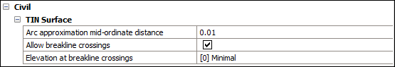
Festlegen der Einstellungen für die TIN-Oberfläche
Bogenannäherung Mitten-Ordinaten Abstand
Note: Der Mitten-Ordinaten Abstand ist der maximale Abstand zwischen Bogen und Sehnensegment (gerade), der für die Bogenannäherung verwendet wird.
Definiert, wie viele Punkte Sie entlang der Kurve hinzufügen möchten. Wenn Sie Polylinien mit Kurven haben, können Sie mit diesem Parameter die Bögen in der Polylinie tesselieren. Der Standardwert dieses Parameters ist in den vordefinierten Vorlagen von BricCAD variabel. Zum Beispiel wird der Abstandswert auf 0.01 in BIM-m, 1 in BIM-cm, 10 in BIM-mm und 0.4 in BIM imperial Vorlagen gesetzt.
Bruchlinien Kreuzungen erlauben
Definiert, ob kreuzende Bruchlinien erlaubt sind. Standardmäßig ist sie auf Ein gesetzt. Wenn Bruchlinienkreuzungen erlaubt sind, werden Schnittpunkte zwischen Bruchliniensegmenten berechnet und als Punkte auf der TIN-Oberfläche hinzugefügt.
Höhe an Kreuzungen der Bruchlinie
Legt fest, wie die Höhe an kreuzenden Bruchlinien bestimmt werden soll. Es gibt drei Optionen (z. B. minimal, maximal und Durchschnitt), um die Höhe der Bruchlinien am Schnittpunkt zu definieren.
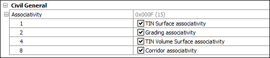
Assoziativität
Aktivieren/deaktivieren Sie die Assoziativität für "Gradierung", "Oberfläche" und "Profilkörper".
Standardmäßig ist die Systemvariable auf 15 eingestellt.
0: Weder TIN-Oberfläche noch Gradierung oder Profilkörper Assoziativität ist aktiviert.
1: Aktiviert die TIN-Oberfläche Assoziativität.
2: Aktiviert die Gradierung Assoziativität.
3: Beide TIN-Oberfläche und Gradierung Assoziativitäten sind aktiviert.
4: Aktiviert die TIN-Volumenoberflächen Assoziativität.
5: Beide TIN-Oberfläche und TIN-Volumenoberfläche Assoziativitäten sind aktiviert.
6: Beide Gradierung und TIN-Volumenoberfläche Assoziativitäten sind aktiviert.
7: TIN-Oberfläche und Gradierung und TIN-Volumenoberfläche Assoziativitäten sind aktiviert.
8: Aktiviert die Profilkörper Assoziativität.
9: Beide TIN-Oberfläche und Profilkörper Assoziativitäten sind aktiviert.
10: Beide Gradierung und Profilkörper Assoziativitäten sind aktiviert.
11: TIN-Oberfläche, Gradierung und Profilkörper Assoziativitäten sind aktiviert.
12: Beide TIN-Volumenoberfläche und Profilkörper Assoziativitäten sind aktiviert.
13: TIN-Oberfläche, TIN-Volumenoberfläche und Profilkörper Assoziativitäten sind aktiviert.
14: Gradierung, TIN-Volumenoberflächen und Profilkörper Assoziativitäten sind aktiviert.
15: Alle Assoziativitäten (TIN-Oberfläche, Gradierung, TIN-Volumenoberfläche und Profilkörper) sind aktiviert.
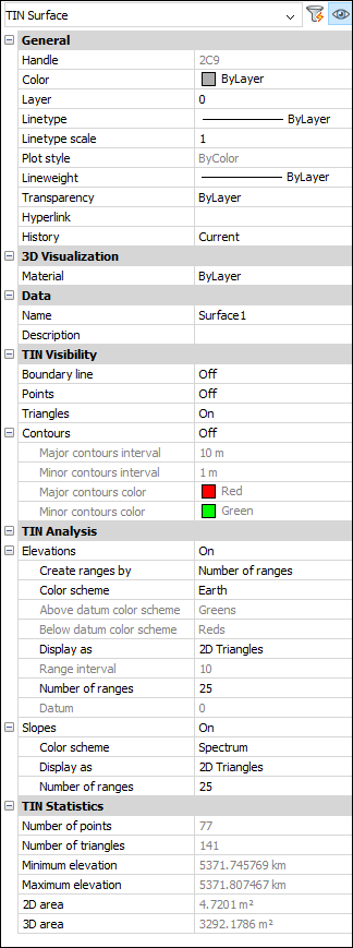
Eigenschaften einer TIN-Oberfläche
TIN-Sichtbarkeit
Defines the visibility of the TIN surface elements.
Umgrenzungslinie
Change visibility of the outer boundary on a TIN Surface.
Punkte
Change visibility of points on a TIN Surface.
Dreiecke
Change visibility of triangles on a TIN Surface.
Konturen
Defines the visibility of contours on a TIN Surface.
Intervall der Hauptkonturen
Legt das Intervall der Hauptkonturen fest.
Intervall der Unterkonturen
Legt das Intervall der Unterkonturen fest.
Hauptkontur Farbe
Definiert die Farbe der Hauptkontur.
Unterkontur Farbe
Definiert die Farbe der Unterkontur.
TIN Analysis
Defines the parameters for displaying elevations and slopes analyses.
Ansichten
If ON, this option defines the parameters for displaying elevations analyses.
Create ranges by
Sets the range type (Number of ranges, Range interval, Range interval with datum).
Color scheme
Sets a color scheme for the elevation analysis.
Above datum color scheme
Sets the above datum color scheme.
Below datum color scheme
Sets the below datum color scheme.
Display as
Sets the type of entities that will be used for displaying elevation analysis (Triangles, Contours, Points, 2D Triangles, 2D Contours)
Range interval
Sets the range interval.
Number of ranges
Sets the number of ranges.
Datum
Sets the datum.
Slopes
If ON, this option defines the parameters for displaying slopes analyses.
Color scheme
Sets the color scheme for slopes.
Display as
Sets the type of entities that will be used for displaying slopes analysis
(Triangles, 2D Triangles).
Number of ranges
Sets the number of ranges.
TIN-Statistiken
Displays the TIN Statistics.
Anzahl der Punkte
Displays the number of TIN Surface points.
Anzahl der Dreiecke
Displays the number of TIN Surface triangles.
Minimale Höhe
Zeigt den minimalen Höhenwert an, der in der TIN-Oberfläche gefunden wird.
Maximale Höhe
Zeigt den maximalen Höhenwert an, der in der TIN-Oberfläche gefunden wurde.
2D-Bereich
Displays the 2D area of the TIN surface.
3D-Bereich
Displays the 3D area of the TIN surface.
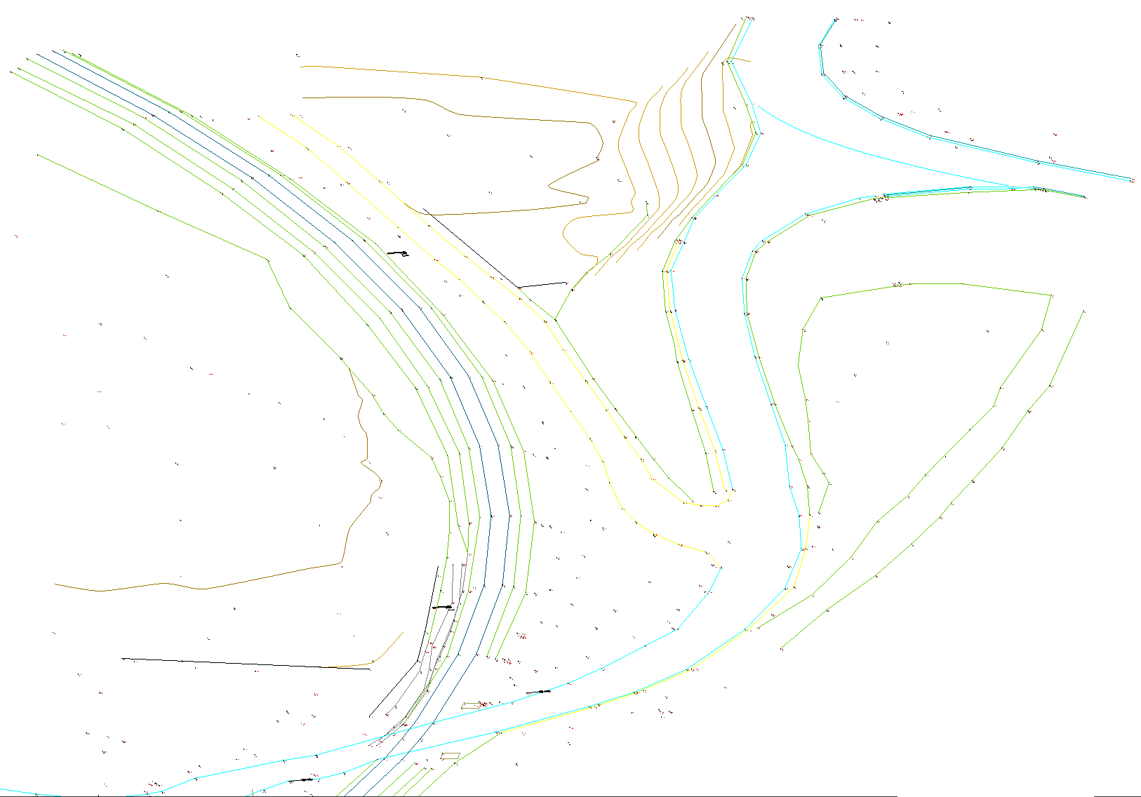
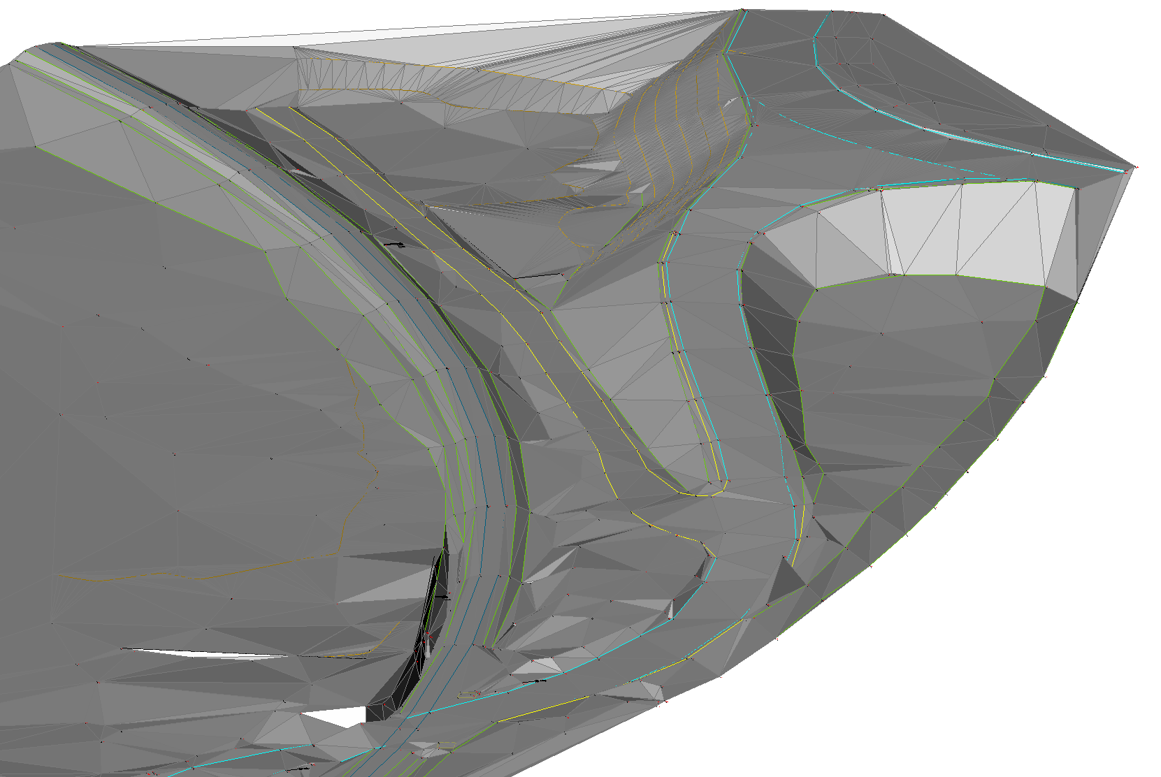
Procedure: Creating a TIN Surface from drawing entities
Open the drawing that contains drawing entities, such as CAD points, blocks and polylines.
Starten Sie den Befehl TIN .
Select all entities in the drawing.
Press ENTER
Select an option in command line to apply selected linear entities as Breaklines.
Note: TIN Surface maintains a live connection to linear drawing entities when they are added as Breaklines. When editing such drawing entities, the TIN surface is automatically rebuilt. If linear drawing entities are added to a TIN Surface as edges or points, this connection is not maintained. The same applies to CAD blocks and points.
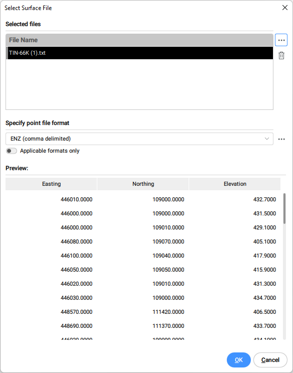
Procedure: Creating a TIN Surface from a point file
Starten Sie den Befehl TIN .
Wählen Sie in der Befehlszeile Importieren aus Datei.
In the Select Surface file dialog box, select the point data file that you want to open, or choose multiple files to import all at once.
Specify point file format from the drop-down list.
Note: click the browse button in the Specify point file format section to manage surface file formats.
Toggle the Applicable formats only to automatically filter appropriate point file formats, according to the selected input point file(s).
Click OK to create TIN Surface from a point file.
Select "No" in a command line to create TIN Surface without simplifying points.
Note: Check the description of the TIN Simplify algorithm for detailed explanation of the parameters.
Procedure: Creating a TIN Surface from a point file using Clip polygon
Use existing or create a new closed polyline to create a TIN Surface inside that area.
Starten Sie den Befehl TIN .
Wählen Sie in der Befehlszeile die Option Schneide-Polygon aus.
Select a closed polyline in a drawing to be used as a clipping polygon.
Select an option Import from file in a command line to create TIN surface from a point file inside the selected clipping polygon.
Note:Note: Select any other option: select (drawing) entities, create from Faces, create from Point Cloud, create from Point Groups.
Follow the procedure for creating a TIN Surface from a point file, which is described in this article.
Note: The TIN surface algorithm connects triangles outside the boundary of the concave clipping polygon. In such areas, long and narrow triangles are created, which can be removed with the TINEDIT command.
Launch the TINEDIT command and select an option "Remove Outer Edges". Then specify the maximum triangle length. Triangles that are longer than specified value are removed.
Verfahren: Erstellen einer TIN-Oberfläche durch Platzieren von Punkten
Öffnen Sie eine Zeichnung.
Starten Sie den Befehl TIN .
Wählen Sie in der Befehlszeile die Option Punkte platzieren.
Wählen Sie einen Punkt, an dem Sie mit der Erstellung einer TIN-Oberfläche beginnen möchten.
Geben Sie den Höhenwert für jeden dieser Punkte an, und drücken Sie dann die EINGABETASTE, um zu akzeptieren.
Note: Zum Erstellen einer TIN-Oberfläche werden mindestens drei Punkte benötigt.
Verfahren: Erstellen einer TIN-Oberfläche aus Flächen
Öffnen Sie eine Zeichnungsdatei, die 3D-Flächen enthält.
Starten Sie den Befehl TIN .
Wählen Sie in der Befehlszeile die Option aus Flächen erstellen.
Wählen Sie die gewünschten 3D-Flächen aus.
Select an option whether to apply 3D Faces as edges (and visibility) or not.
Note: If this option is selected, then edges and vertices of the 3D Faces are used to create the TIN surface. Otherwise, only the vertices of the 3D faces are used to create the TIN surface. As a result, the TIN Surface does not follow the edges of the 3D Faces.
Verfahren: Erstellen einer TIN-Oberfläche aus einer Punktwolke
Öffnen Sie die Zeichnungsdatei, die eine Punktwolke enthält.
Starten Sie den Befehl TIN .
Select an option "Create from point cloud" in a command line.
Select a point cloud in the drawing.
Drücken Sie die EINGABETASTE.
Select "No" to create TIN Surface without using the simplification method.
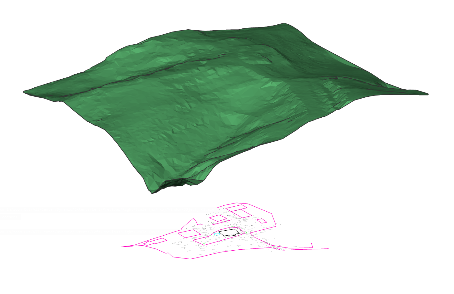
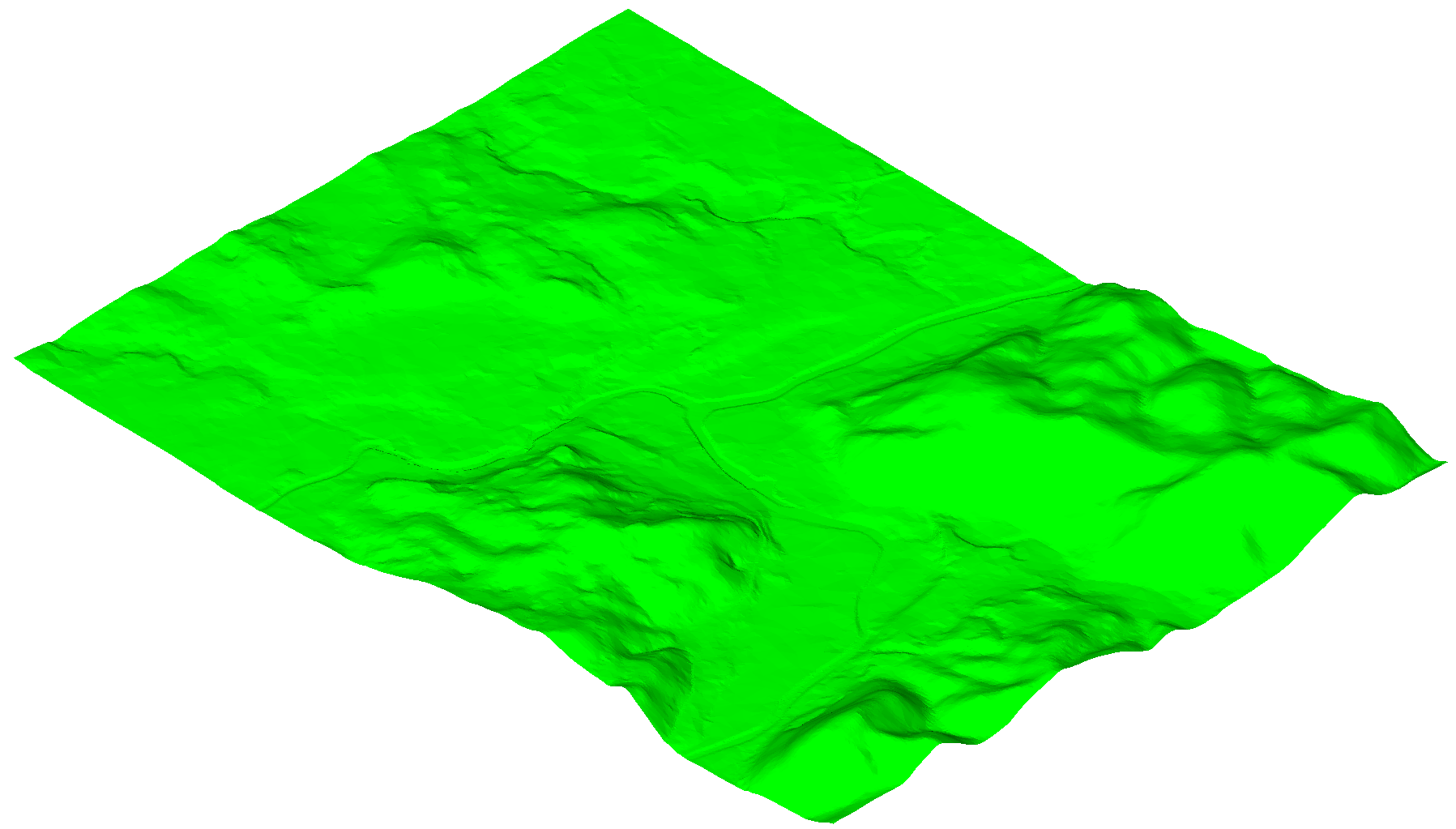
Image shows original TIN Surface created from a Point Cloud with 87350 points.
Procedure: Use TIN Simplify and TIN Densify options when creating TIN Surface from a Point Cloud
This section describes the procedure of creating a TIN Surface from a Point Cloud, where we also use the TIN Simplify and TIN Densify options.
Follow steps 1 to 5 from the procedure described above to create a TIN surface from a Point Cloud. Then, follow the procedure below to use TIN Simplify and TIN Densify options.
Select "Yes" when command line offers the option to simplify TIN surface.
Enter radius for simplification step.
Enter Elevation difference.
Note: Check the description of the TIN Simplify algorithm for detailed explanation of the parameters.
Select "Create TIN Surface" in a command line.
Or select an option "Simplify again" to edit the simplification parameters.
Note: The command line reports the number of points before and after simplification so that the user can make a better decision for the next steps.
Select "Yes" to Densify TIN Surface.
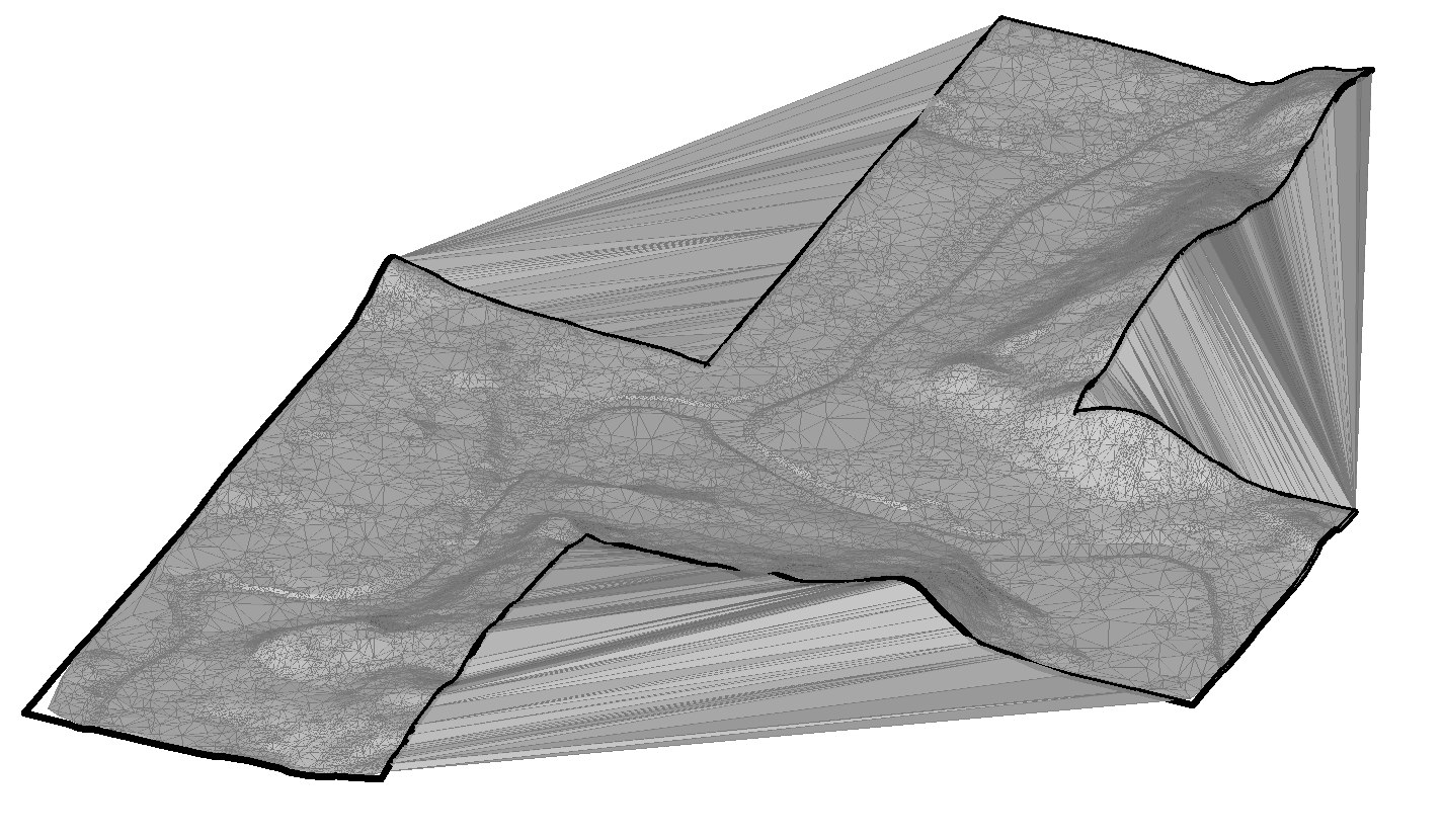
Or select "No" to create simplified TIN Surface.Image Shows simplified TIN Surface with 1562 points.
Enter elevation difference.
Select one of the options to specify the area for TIN Densify process: select existing polygons in a drawing, draw a new polygon or press ENTER to use entire TIN Surface.
Note: Check the description of the TIN Densify algorithm for detailed explanation of the parameters.
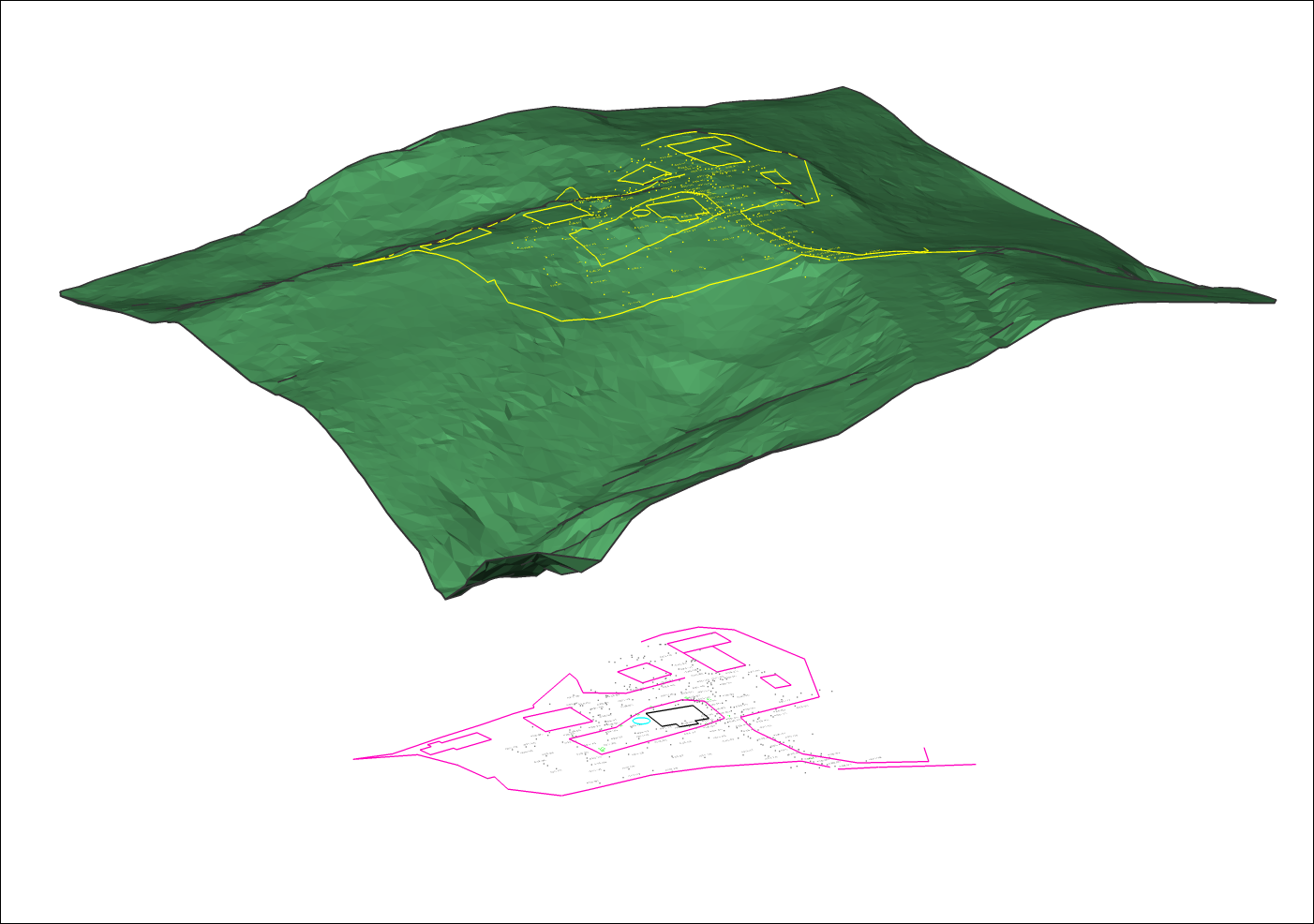
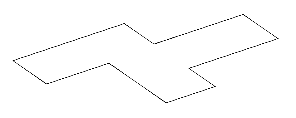
Image shows a polygon that defines an area for TIN densification.
Note: The final result represents a simplified TIN surface to which individual points within the specified polygon are returned. By using TIN Densify option on a specific area on the entire TIN Surface, we achieve the goal that in this area the elevation difference between the original and the final TIN surface is never greater than the specified value of the "elevation difference" in step 6.
Image shows a final TIN Surface with 6536 points. Original TIN Surface consists of 87350 points.
Note: You can edit the TIN Simplify and TIN Densify parameters at any time in Civil Explorer. Select the appropriate TIN Surface, right-click on the "Add points" definition and select "Edit" option from the context menu. The Surface definition dialog box opens in which you can edit all the necessary parameters.
Verfahren: Erstellen einer TIN-Oberfläche aus einer Civil 3D-Oberfläche
Öffnen Sie eine Zeichnung mit einer Civil 3D-Oberfläche.
Launch the CIVIL3DIMPORT command.
In the Import Civil 3D dialogue box, select Convert from current drawing.
Note: Select AutoCAD Civil 3D Surfaces that will be converted to BricsCAD Civil TIN Surfaces.
Note: In the "Import Civil 3D" dialog box, you can also select other Civil 3D objects, such as Point Groups, Alignments and Profiles, that will be converted to BricsCAD Civil elements.
Specify the name template for Civil 3D objects.
Tick the option Import Civil 3D labels as blocks.
Click the OK button.
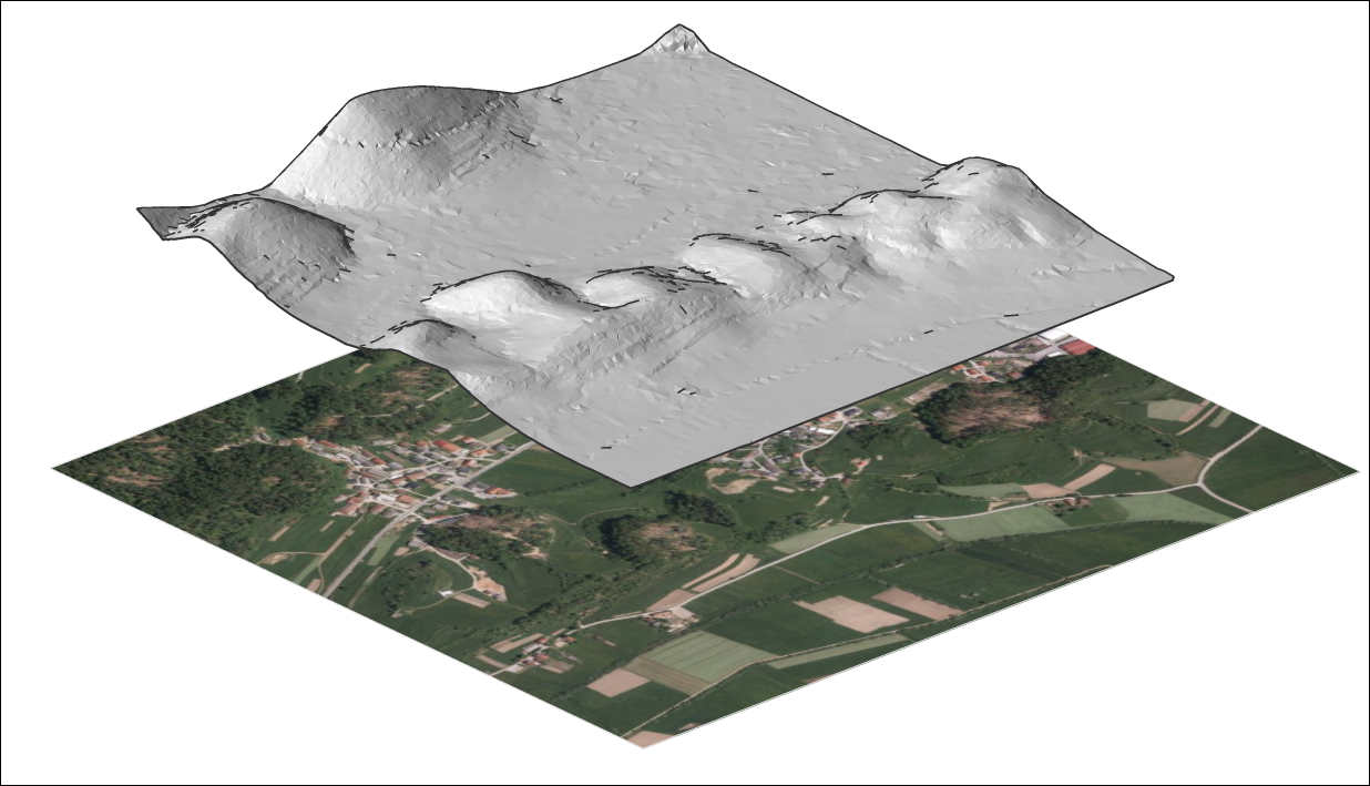
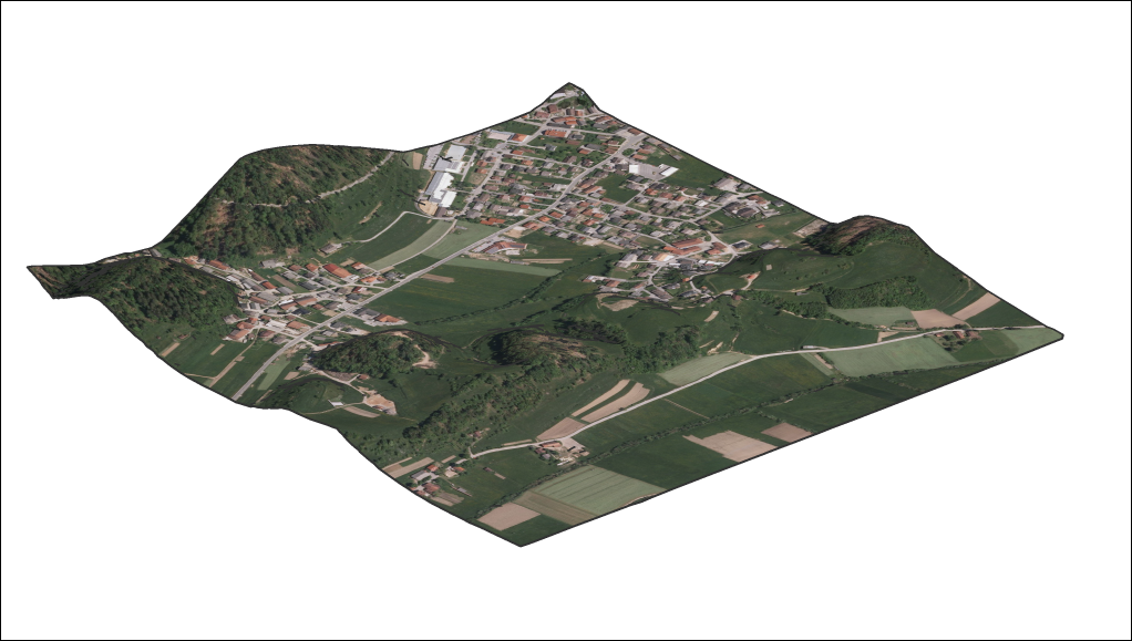
Über TIN-Bild zuordnen
Öffnen Sie die Zeichnungsdatei, die eine TIN-Oberfläche und ein Bild enthält.
Starten Sie den Befehl TINZUORDBILD.
Wählen Sie die TIN-Oberfläche.
Wählen Sie das Rasterbild aus.
Note: Wird das Bild nicht auf der TIN-Oberfläche angezeigt, ändern Sie den visuellen Stil in Modellierung oder Realistisch und stellen Sie die Dreiecke der TIN-Oberfläche auf EIN.
Über TIN-Projekt
Öffnen Sie die Zeichnungsdatei, die die TIN-Oberfläche und die Objekte (Punkte, Blöcke, Text, Linien, Polylinien, Kreise…) enthält.
Starten Sie den Befehl TINPROJEKT.
Zu projizierende Objekte auswählen.
Wählen Sie aus, ob die ursprünglichen Objekte gelöscht werden sollen.


 Note: The TIN surface algorithm connects triangles outside the boundary of the concave clipping polygon. In such areas, long and narrow triangles are created, which can be removed with the TINEDIT command.
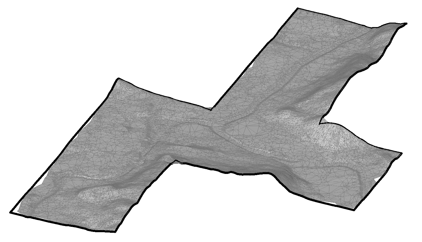
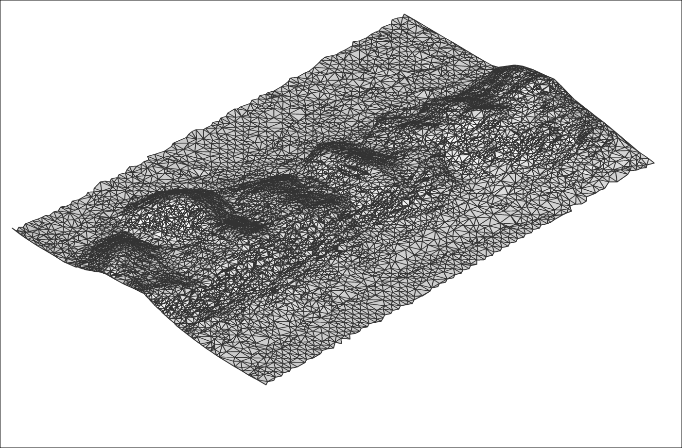
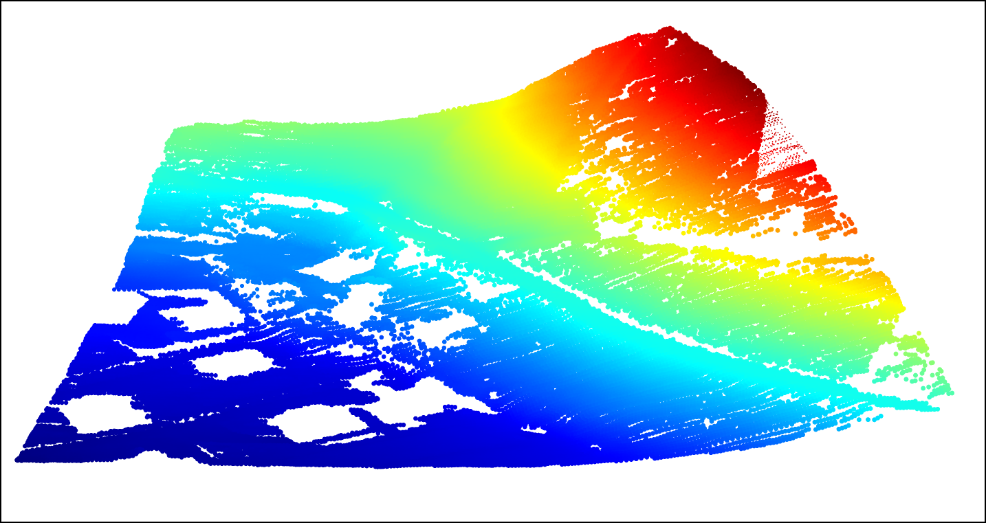
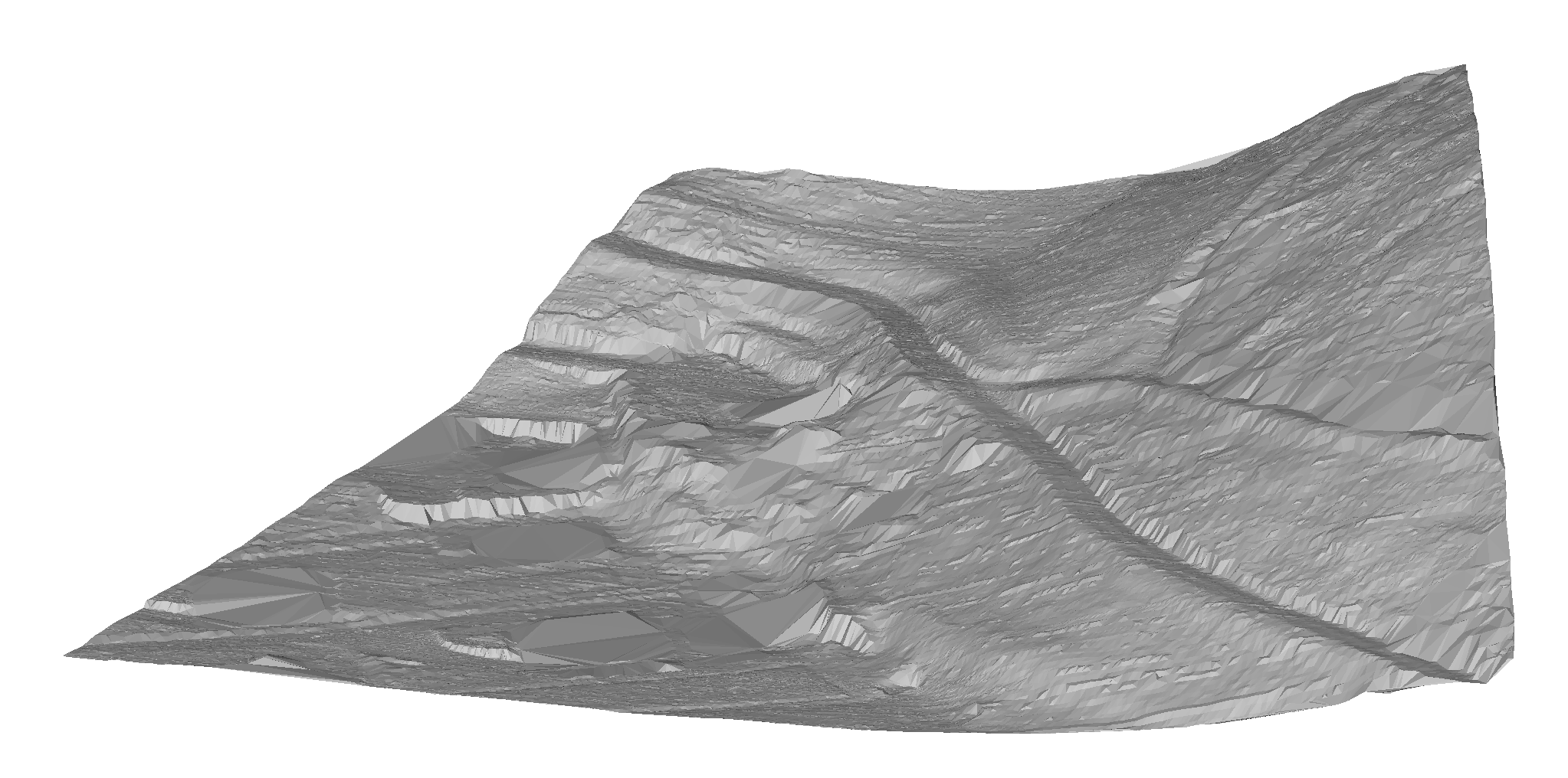
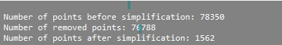
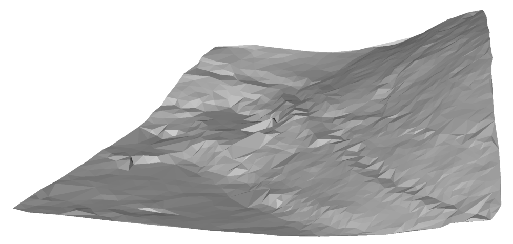
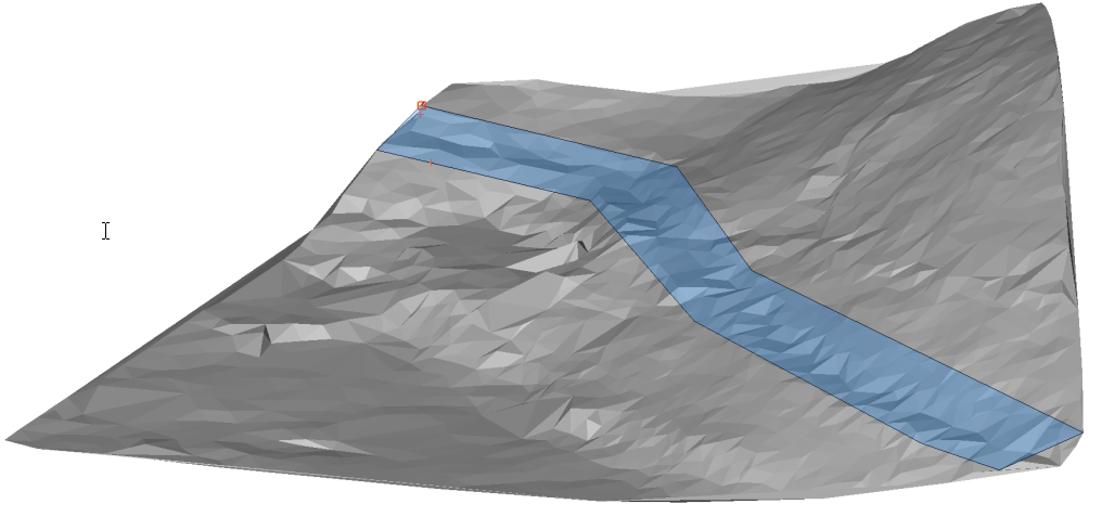 Image shows a polygon that defines an area for TIN densification.Note: The final result represents a simplified TIN surface to which individual points within the specified polygon are returned. By using TIN Densify option on a specific area on the entire TIN Surface, we achieve the goal that in this area the elevation difference between the original and the final TIN surface is never greater than the specified value of the "elevation difference" in step 6.
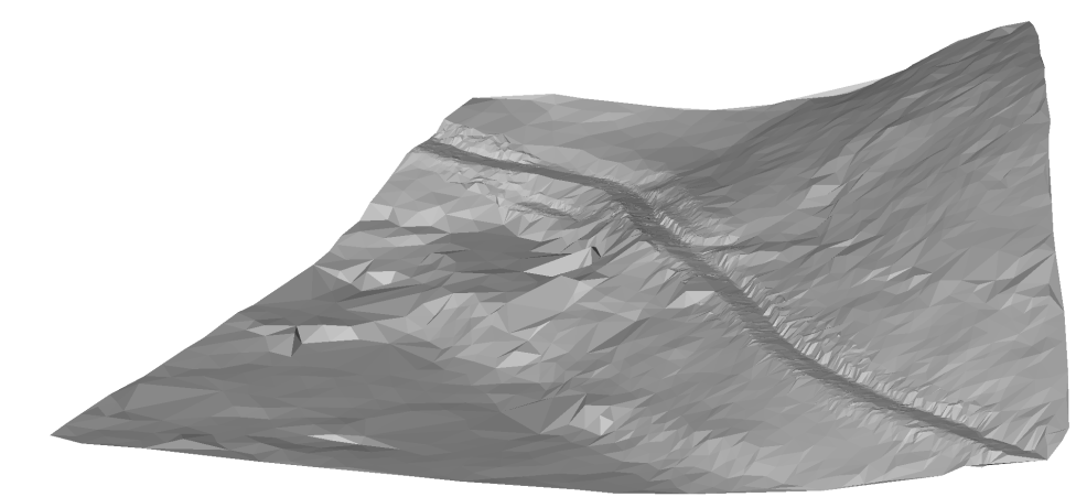 Image shows a final TIN Surface with 6536 points. Original TIN Surface consists of 87350 points.Note: You can edit the TIN Simplify and TIN Densify parameters at any time in Civil Explorer. Select the appropriate TIN Surface, right-click on the "Add points" definition and select "Edit" option from the context menu. The Surface definition dialog box opens in which you can edit all the necessary parameters.
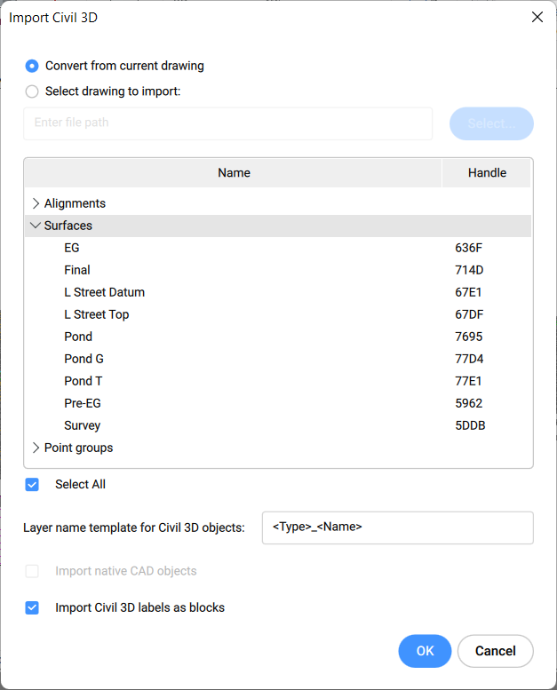
 Note: Wird das Bild nicht auf der TIN-Oberfläche angezeigt, ändern Sie den visuellen Stil in Modellierung oder Realistisch und stellen Sie die Dreiecke der TIN-Oberfläche auf EIN.