


Dynamic UCS
With the Dynamic UCS feature enabled, the coordinate system is aligned automatically with the entity under the cursor.
The UCSDETECT system variable controls the supported entity types:
- Faces of 3d Solids, surfaces, subdivision meshes and regions (the default).
- Other entity types: point, line, polyline, 2D polyline, 3D polyline, ray, xline, arc, circle, ellipse, spline, text, mtext, solid, 3Dface, trace, block insert, viewport, mline, leader, mleader, hatch, helix, camera, light, section, shape, pdf underlay and image.
Right click the DUCS field in the status bar to select the supported entity types.
Entities can be selected inside blocks, except curved faces of ACIS entities in non-uniformly scaled blocks.
These features are controlled by user preferences.
- RedHilite_DUCSLocked_Face_Color controls the highlight color for the face to which the Dynamic UCS has been locked by pressing the Shift key.
- RedHilite_DUCSLocked_Face_Alpha controls the highlight transparency for the face to which the Dynamic UCS has been locked by pressing the Shift key.
Toggling the dynamic UCS
Do one of the following:
- Press the F6 function key.
- Click the DUCS field in the status bar.
Using the Dynamic UCS
- With the Dynamic UCS feature active, launch an entity creation command, for example LINE.
-
Move the cursor over an entity or 3D solid face.
The entity or face highlights.
If GRIDMODE is On, the grid is aligned with the hovered entity or face.
- If UCSICON = 3 (On at Origin), the UCS icon displays.
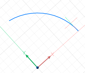
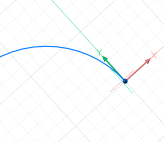
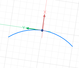
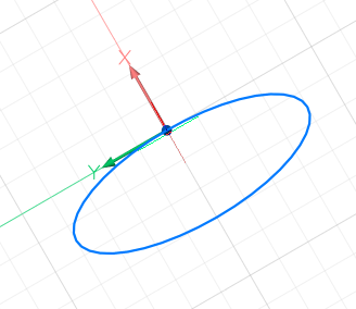
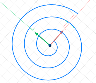
Dynamic UCS on other entities 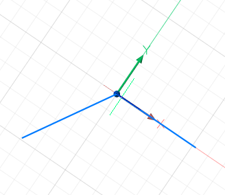
Dynamic UCS on 3D solid faces 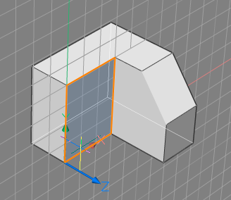
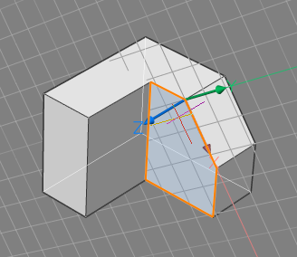
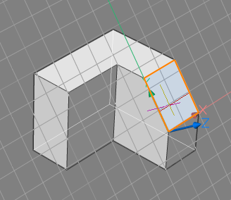
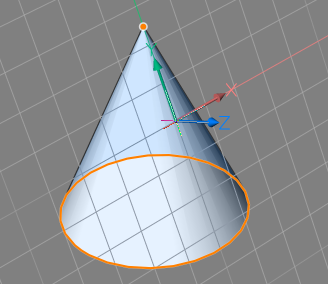
The orientation of dynamic UCS depends on how the cursor touches the hovered entity or face This provides users a way to manipulate the orientation of the DUCS. On 3D solid faces, the origin of the DUCS is set to the starting point of the solid edge and the X-axis is chosen co-directional to the tangent at the starting point of the edge. On curved faces, the X-axis is tangent to the face, the Y-axis lies in the face and the Z-axis is perpendicular to the face.
- (option) Tap the Shift key to lock the DUCS, which allows you to start drawing outside the hovered entity or face. Tap the Shift key again to unlock the DUCS.
- Execute the entity creation command. Note: When bitcode 2 of the OSOPTIONS system variable is selected, entity snap ignores negative Z-values in the current UCS.
- When the command concludes, the current coordinate system (WCS or UCS) is restored.