Using dimensional constraints
Dimensional constraints control the dimensions of 2D entities.
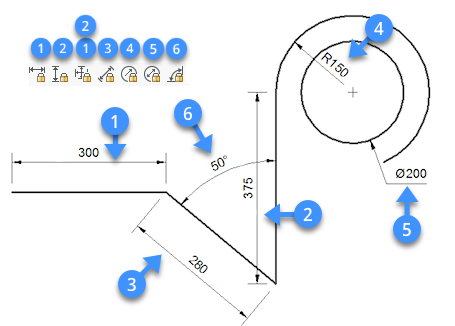
- Horizontal distance (1) (DCLINEAR and DCHORIZONTAL commands).
- Vertical distance (2) (DCLINEAR and DCVERTICAL commands).
- Distance between points or the length of lines and polyline segments (3) (DCALIGNED command).
- Radius of arcs, circles and arc polyline segments (4) (DCRADIUS command).
- Diameter of arcs, circles and arc polyline segments (5) (DCDIAMETER command).
- Angle between entities or between points and entities (6) (DCANGULAR command).
Editing dimensional constraints
Dimensional constraints can be edited:
- In the Properties panel.
- In the Mechanical browser panel.
- In the Parameters Manager panel.
- Using the DDEDIT command.
Editing dimensional constraints in the Properties panel
-
Select the dimensional constraint.
The properties of the entity display in the Properties panel.
-
Type a new value or expression in the Expression field, then press Enter.
The readout of the Value field changes accordingly.
-
(option) Edit the Name field.
-
(option) Edit the Description field.
-
(option) Edit the Text rotation field.
-
Press the Esc key to unselect.
Editing dimensional constraints in the Mechanical browser panel
-
If not already open, open the Mechanical Browser panel.
-
Select a name of the dimensional constraint in the Parameters list.
The properties the selected parameter display in bottom part of the Mechanical browser panel.
-
(option) Select the Name field, then type a new name.
-
(option) Select the Expression field, then type a new value or expression.
-
(option) Select the Description field, then type a new description.
-
(option) Set the Exposed field, which specifies whether the parameter is exposed when the drawing is inserted in another drawing using the BMINSERT command.
The options are:- Auto: the parameter is exposed only if it does not depend on other parameters.
- ON: the parameter is always exposed.
- OFF: the parameter is never exposed.
-
(option) Set the Units property: linear, planar or volume.
Select the field, then click the down-arrow button and choose an option.
Using the DDEDIT command
-
Do one of the following:
- Double click the dimensional constraint.
- Launch the DDEDIT command.
You are prompted: _DDEDIT
The Edit Text dialog box displays.
-
Type a new value in the Text field, then press Enter or click the OK button.
-
(option) Click another dimensional constraint and repeat the previous step.
-
Do one of the following:
-
Keep editing more dimensional constraints.
-
Press Enter or right click to stop.
All edited dimensional constraints are updated simultaneously.
-
Setting the visibility of dimensional constraints
Dimensional constraints are hidden when a drawing is closed and reopened.
- The Dimensional Constraint toolbar.
- the Parametric ribbon tab.
- the Show/Hide 2D Constraints fly-out menu of the Parametric menu.
These tools execute the DCDISPLAY command using a specific option.
The options are:
- Show/Hide: prompts you to select the entities.
- Show All: show all dimensional constraints in the drawing.
- Hide All: hide all dimensional constraints in the drawing.
-
The DYNCONSTRAINTMODE system variable controls the visibility of hidden dimensional constraints when selecting entities:
- ON: display dimensional constraints when entities are selected.
- OFF: dimensional constraints remain hidden when entities are selected.
-
When hovering over an entity with a dimensional constraint, the blue constraint glyph (
 ) displays if the SELECTIONPREVIEW system variable is set to 1 or 3 or when the Quad is active.
Using expressions to define dimensional constraints
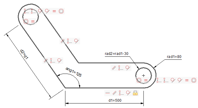
Dimensional constraints are named automatically upon creation.
The naming rules are as follows:
- distance: d1, d2, d3, ...
- radius: rad1, rad2, rad3, ...
- diameter: dia1, dia2, dia3, ..
- angular: ang1, ang2, ang3, ..
The name of a constraint can be used as a parameter in a mathematical expression to define another dimensional constraint.
The dimensions of the bracket below are controlled through the rad1 radius, d1 distance and ang1 angular dimensional constraints.
The radius of the hole (rad2 ) and the length of the second leg (d2 ) are defined by expressions.
Geometrical constraints force the width of the second leg and the hole in it to be equal to the first leg.
Using operators in expressions
The following operators can be used in expressions:
| Operator | Description |
|---|---|
| + | Addition |
| - | Subtraction or Negative |
| * | Multiplication |
| / | Division |
| ^ | Exponentiation |
| % |
Modulo or Remainder operator The expression "5 % 2" would evaluate to 1, because 5 divided by 2 leaves a quotient of 2 and a remainder of 1. |
Expressions are evaluated according to the standard mathematical rules of precedence:
- Expressions within brackets; innermost sets first.
- Standard operations order:
- exponent
- multiplication and division
- addition and subtraction
- Operators of equal precedence from left to right.
Using functions in expressions
The following functions can be used in expressions:
| Function | Syntax |
|---|---|
| Cosine | cos(expression) |
| Sine | sin(expression) |
| Tangent | tan(expression) |
| Arc cosine | acos(expression) |
| Arc sine | asin(expression) |
| Arc tangent | atan(expression) |
| Hyperbolic cosine | cosh(expression) |
| Hyperbolic sine | sinh(expression) |
| Hyperbolic tangent | tanh(expression) |
| Arc hyperbolic cosine | acosh(expression) |
| Arc hyperbolic sine | asinh(expression) |
| Arc hyperbolic tangent | atanh(expression) |
| Square root | sqrt(expression) |
| Signum function (-1,0,1) | sign(expression) |
| Round to nearest integer | round(expression) |
| Truncate decimal | trunc(expression) |
| Round down | floor(expression) |
| Round up | ceil(expression) |
| Absolute value | abs(expression) |
| Largest element in array | max(expression1;expression2)* |
| Smallest element in array | min(expression1;expression2)* |
| Degrees to radians | d2r(expression) |
| Radians to degrees | r2d(expression) |
| Logarithm, base e | ln(expression) |
| Logarithm, base | 10 log(expression) |
| Exponent, base e | exp(expression) |
| Exponent, base 10 | exp10(expression) |
| Power function | pow(expression1;expression2) 1 |
| Random decimal, 0-1 | Random |
* Use the list separator character as defined on your system: , (comma) or ; (semicolon).
Creating a new parameter
-
Right click Parameters in the Mechanical Browser panel.
A context menu displays.
-
Select Add new parameter in the context menu.
A new parameter is created.
-
Edit the properties of the new parameter.
See the Editing dimensional constraints in the Mechanical browser panel procedure above.
- The constants Pi=3.14... and e=2.72... can be used in expressions. The constants names are not allowed to be used as a parameter or constraint name.
- The CLEANUNUSEDVARIABLES command purges parameters that are not used in constraint expressions or linked to dimensions.