Details parametrisieren
Befehle
BIMPARAMETRIERENDETAIL
Über BIMPARAMETRIERENDETAIL
Mit dem Befehl BIMPARAMETRIERENDETAIL erzeugen Sie automatisch Parameter für ein gespeichertes Detail. Es werden Standardparameter wie Winkel, Versätze in verschiedenen Richtungen und Toleranzparameter erstellt. Mit diesen Parametern können Sie Details auf Zielsituationen übertragen, ähnlich wie im folgenden Beispiel.
Die automatisch generierten Parameter bilden einen Rahmen, der die Position und Form der Referenz-Volumenkörper steuern kann. Sie können diesen Rahmen um benutzerdefinierte Abhängigkeiten erweitern. Sie können die Auswirkungen dieser Änderungen durch die Animation der Parameter aus dem Mechanical Browser überprüfen. Sie können benutzerdefinierte Abhängigkeiten hinzufügen, um Detailobjekte mit den Referenz-Volumenkörpern und untereinander zu verbinden. Sie können den Rahmen auch im Ausdruck dieser Abhängigkeiten verwenden.
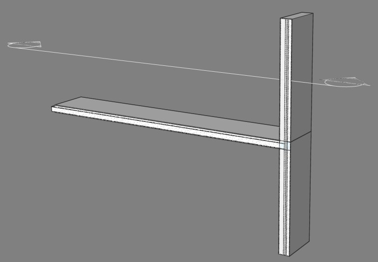
Parametrisieren und Bearbeiten eines Wand-Platte-Verbindungsdetail
- Um die DWG-Datei des Details zu öffnen, das Sie parametrisieren möchten, klicken Sie auf das Detail im Panel Details. Der Dialog Details anzeigen wird angezeigt.
- Klicken Sie auf Parametrisieren oder klicken Sie auf Öffnen und führen Sie BIMPARAMETRIERENDETAIL aus. Das Detail-DWG-Datei wird geöffnet und das Detail wird parametrisiert.
- Öffnen Sie das Panel Mechanical Browser.
- Klicken Sie im Werkzeug-Panel auf die Schaltfläche Mechanical Browser.
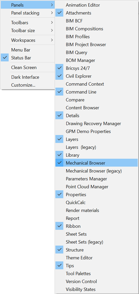
- Wenn die Schaltfläche Mechanical Browser noch nicht sichtbar ist, bewegen Sie den Cursor auf dem Werkzeugkasten oder dem Multifunktionsleisten-Panel und klicken Sie mit der rechten Maustaste. Ein Kontextmenü wird angezeigt.
Erweitern Sie die Option Panels.
Wählen Sie im Kontextmenü Mechanical Browser aus.
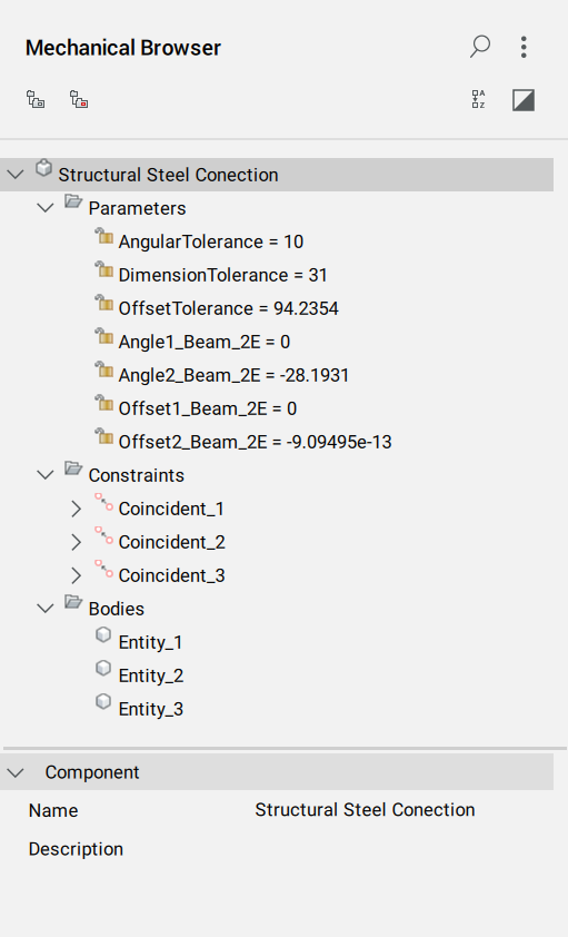
- Sobald Sie auf die Schaltfläche Mechanical Browser geklickt haben, wird der Mechanical Browser angezeigt:
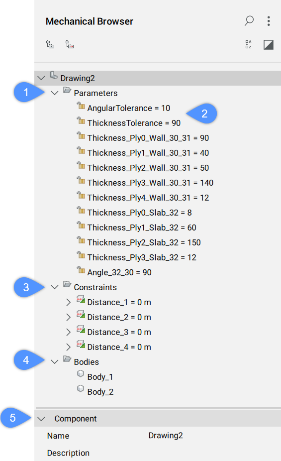
Anmerkung: Sie können auch den Befehl MECHANICALBROWSERÖFFNEN verwenden.Parameter (1): Klicken Sie mit der rechten Maustaste auf einen Parameter, um ein Kontextmenü zu öffnen:
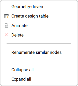
- Geometrie getrieben: Wenn diese Option aktiviert ist, wird der Parameter von der Geometrie getrieben.
- Design-Tabelle erstellen: Erstellt eine Designtabelle zur Steuerung der Parameter des parametrischen Blocks.
- Animieren: Animiert Modelle anhand von Parametern.
- Löschen: Löscht den ausgewählten Parameter.
- Ähnliche Knoten renummerieren: Renummeriert alle Knoten des gleichen Typs und der gleichen Ebene.
- Alle zuklappen: Reduziert den gesamten Mechanical Browser.
- Alle erweitern: Erweitern Sie den gesamten Mechanical Browser.
Toleranzparameter (2): Zeigt die maximale und minimale Abweichung eines Winkels, einer Stärke oder einer Abmessung vom ursprünglichen Parameterwert an.
Abhängigkeiten (3): Enthält Abhängigkeiten, die Sie löschen, ändern oder hinzufügen können.
Anmerkung: Es werden einige standard Abhängigkeiten generiert, die das Detailvolumen und die Detailobjekte mit den Referenzvolumenkörpern verknüpfen. Sie können sie löschen und durch andere Abhängigkeiten ersetzen.Körper (4): Zeigt die Körper im Modell an.
Komponente (5): Zeigt die Eigenschaften der Detaildatei an.
- Bearbeiten Sie die Parameter.
Die generierten Parameter haben bestimmte Werte, um sicherzustellen, dass das Detail genau so aussieht, wie es erstellt wurde. Wenn Sie diese Werte ändern, ändert sich das Detail.
Zum Beispiel:
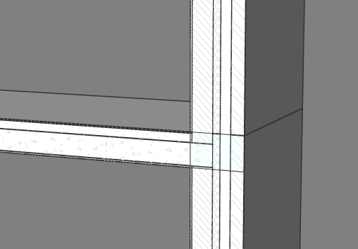
- Ändern Sie den Parameter Thickness_Ply1_Wall_30_31 von 40 auf 70 (im Feld Ausdruck). Das neue Detail unterscheidet sich im Modelbereich sichtbar:
Vorher Danach 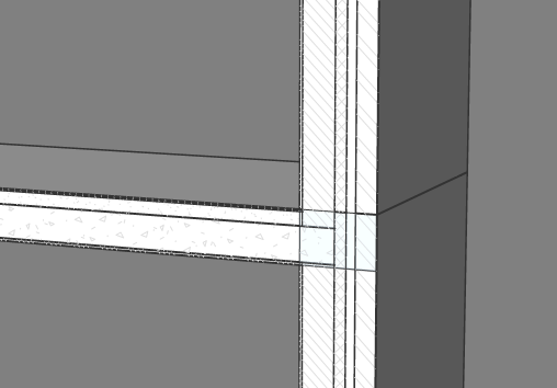
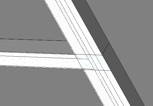
- Ändern Sie den Parameter Angle_32_30 von 90 auf 120. Der neue Winkel zwischen Wand und Platte ist im Modelbereich anders.
Es erscheint eine Warnung:
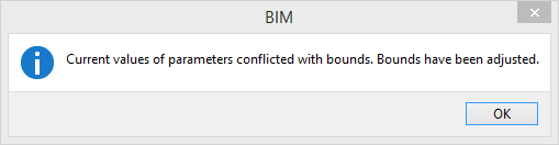
Dies liegt daran, dass der Parameter AngularTolerance auf 10 gesetzt wurde. Der neue Parameter AngularTolerance ändert sich automatisch auf 30, da Sie den Parameter Angle_30_31 um 30 Grad geändert haben.
- Klicken Sie auf OK
Vorher Danach
- Ändern Sie den Parameter Thickness_Ply1_Wall_30_31 von 40 auf 70 (im Feld Ausdruck). Das neue Detail unterscheidet sich im Modelbereich sichtbar:
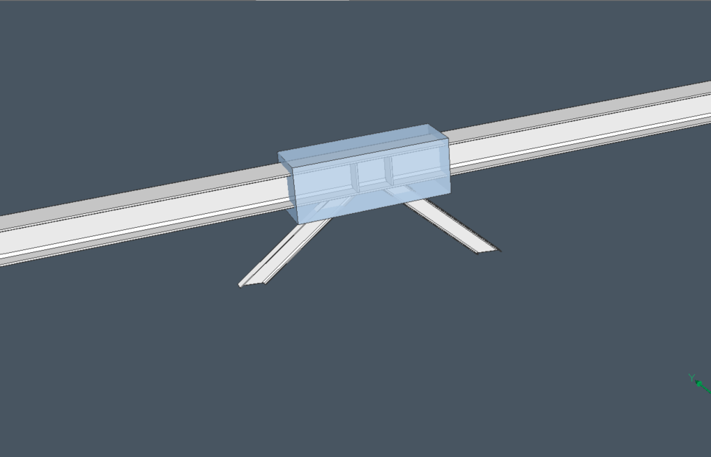
Strukturelle Stahlverbindung parametrieren und bearbeiten
- Um die DWG-Datei des Details zu öffnen, das Sie parametrisieren möchten, klicken Sie auf das Detail im Panel Details. Der Dialog Details anzeigen wird angezeigt.
- Klicken Sie auf Parametrisieren oder klicken Sie auf Öffnen und führen Sie BIMPARAMETRIERENDETAIL aus.
Das Detail-DWG-Datei wird geöffnet und das Detail wird parametrisiert.

- Öffnen Sie das Panel Mechanical Browser:
Anmerkung: Bei Verbindungen zwischen linearen Referenzkörpern werden nur die Rahmenparameter automatisch generiert. Sie müssen Abhängigkeiten manuell hinzufügen, um das Verhalten von Detailobjekten in Bezug auf die Referenzkörper festzulegen. In diesem Beispiel wurden drei Koinzidenz-Abhängigkeiten manuell hinzugefügt: zwei, um sicherzustellen, dass die Verbindungsebenen der dreieckigen Stahlplatte mit den Laschen der Stahlsäule und des Trägers übereinstimmen, und eine, um sicherzustellen, dass der Endabschnitt des Trägers mit der Stützenlasche übereinstimmt. Sie können Koinzidenz-Abhängigkeiten vor oder nach dem Parametrieren-Werkzeug hinzufügen. Wenn Sie anschließend die Koinzidenz-Abhängigkeiten hinzufügen, können Sie sehen, wie sich die Referenzkörper mit neuen Parametern ändern. Dadurch wird deutlich, welche Abhängigkeiten hinzugefügt werden müssen, damit sich alle Detailobjekte korrekt bewegen. - Parameter bearbeiten.
Die generierten Parameter verfügen über spezifische Werte, die sicherstellen, dass das Detail genau so aussieht, wie es erstellt wurde. Wenn Sie diese Werte ändern, ändert sich das Detail.
Zum Beispiel:
- Change the Angle2_Beam_2E from -28.1931013282 to -40. Die Stütze und der Träger ändern sich im Modelbereich.
Es erscheint eine Warnung:
Dies liegt daran, dass der Parameter AngularTolerance auf 10 gesetzt wurde. Der Parameter AngularTolerance wurde automatisch auf 11.8069 geändert, da Sie den Parameter Angle2_Beam_2E um 11.8069 Grad geändert haben. Klicken Sie auf OK.
Vorher Danach 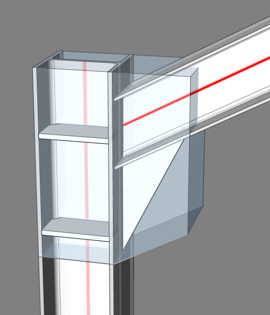

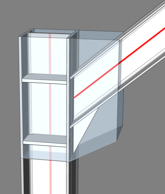
- Ändern Sie Offset1_Beam_2E von 0 auf 200. Sie sehen, dass sich der Träger 200 mm nach unten bewegt.
Es erscheint eine Warnung:
Dies liegt daran, dass der Parameter OffsetTolerance auf 31 gesetzt wurde. Der Parameter OffsetTolerance wurde automatisch auf 200 geändert, da Sie den Parameter Offset1_Beam_2E um 200 mm geändert haben. Klicken Sie auf OK.
Vorher Danach 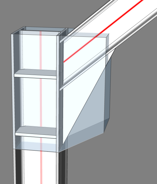
- Change the Angle2_Beam_2E from -28.1931013282 to -40. Die Stütze und der Träger ändern sich im Modelbereich.
Ein Detail in einem Projekt übertragen
Es gibt verschiedene Methoden, ein Detail zu übertragen:
- Mit dem Panel Details: Geben Sie ein Detail aus dem Projekt an alle ähnlichen Verbindungen im Projekt weiter.
- Mit dem Befehl BIMÜBERTRAGEVONDATEI: Ein Detail aus einer Datei übertragen.
Der Befehl BIMÜBERTRAGE liefert weniger Vorschläge für ein Detail, das nicht parametrisiert ist. Dies liegt daran, dass ein nicht parametrisiertes Detail weniger mögliche Standorte hat.
Beispiel: Wenn ein nicht parametrisiertes Detail einer Wand-Platte-Verbindung übertragen wird, kann BricsCAD BIM dieses Detail nicht auf eine Wand-Platte-Verbindung übertragen, wenn die Zusammenstellung unterschiedlich ist oder eine bestimmte Schicht in der Wand um 10 mm abweicht von der entsprechenden Lage in der Wand des Originaldetails. Um dieses Problem zu lösen, parametrisieren Sie das Detail.
Der Befehl BIMÜBERTRAGE kann ein Detail mit Parametern an Situationen anpassen, die vom Original abweichen (z. B. eine andere Ecke, ein kleineres Profil usw.). Mit den Toleranzparametern können Sie entscheiden, wie stark die Verbindungen vom Original abweichen dürfen.
Verschiedene Toleranzparameter:
- Winkel: Legt die Toleranz für Winkelparameter des Details in Grad fest. Winkel in der Zielsituation dürfen von den ursprünglichen Winkeln im Detail nicht um mehr als diesen Toleranzwert abweichen.
- Bemaßung: Legt die Toleranz für die Profilabmessungen linearer Referenzkörper im Detail fest. Profilbreiten und -höhen in der Zielsituation dürfen nicht um mehr als diese Toleranz von den ursprünglichen Breiten und Höhen im Detail abweichen.
- Versatz: Legt die Toleranz für Versatz-Parameter des Details fest. Versätze in der Zielsituation dürfen nicht um mehr als diesen Toleranzwert von den ursprünglichen Versätzen im Detail abweichen.
- Stärke: Legt die Toleranz für die Gesamtstärke planarer Referenzvolumenkörper im Detail fest. Stärken in der Zielsituation dürfen nicht um mehr als diesen Toleranzwert von den ursprünglichen Stärken im Detail abweichen.
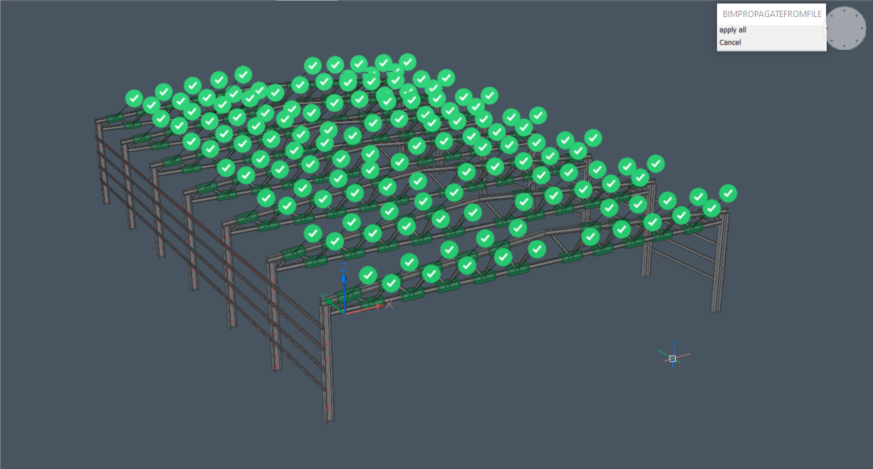
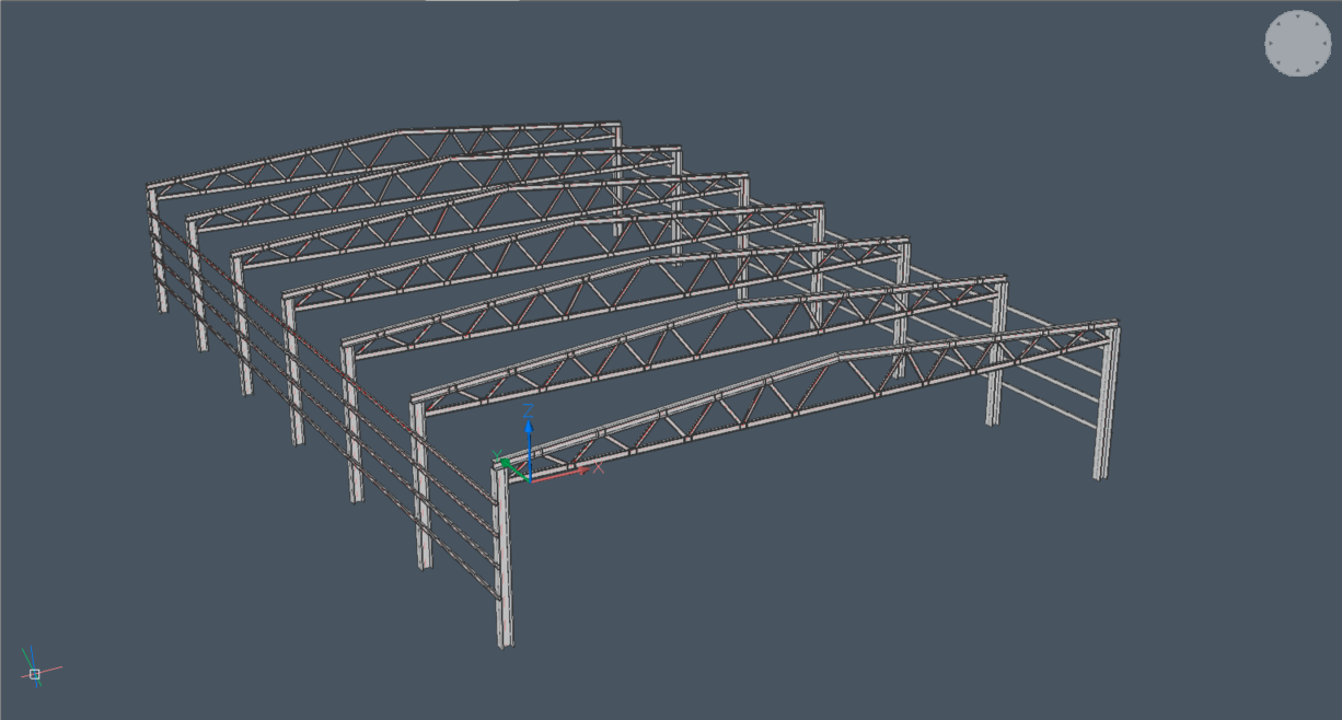
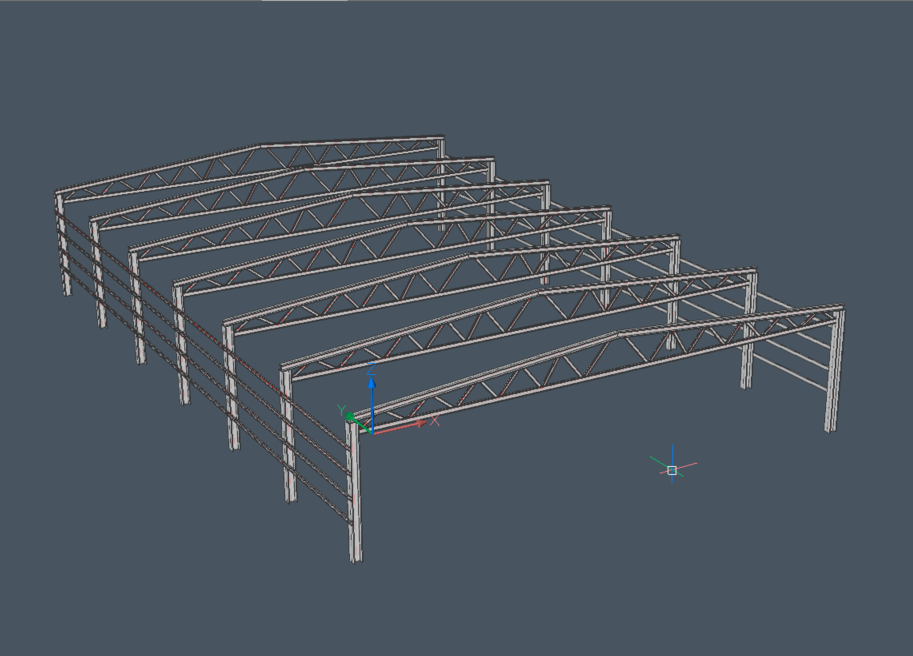
Im folgenden Projekt sind viele ähnliche Verbindungen vorhanden. Allerdings variieren die Winkel der Verbindungen und der untere Träger im Fachwerk hat eine andere Profilgröße als der obere Träger.
Ein Detail in einem Projekt übertragen:
Das Panel Mechanical Browser zeigt die Parameter an. Der Parameter AngularTolerance ist auf 0 Grad eingestellt. Das Detail wird nur auf Verbindungen mit genau demselben Winkel übertragen.
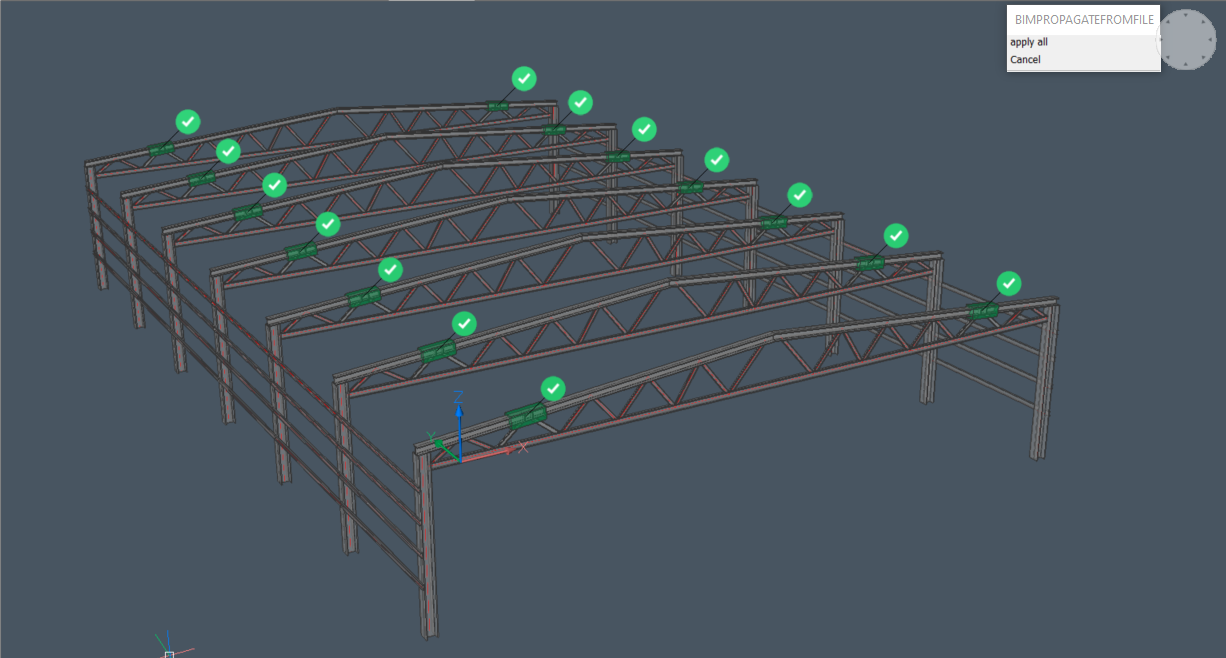
Ändern Sie den Parameter AngularTolerance auf 45 Grad. Das Detail wird auf alle ähnlichen Verbindungen übertragen. Dies liegt daran, dass keine der Verbindungen den Toleranzwert überschreitet.