Parametrize details
Commands
BIMPARAMETRIZEDETAIL
About BIMPARAMETRIZEDETAIL
Use the BIMPARAMETRIZEDETAIL command to automatically generate parameters for a saved detail. Standard parameters, such as angles, offsets in different directions and tolerance parameters are created. These parameters mean you can propagate details to target situations similar to the example below.
The automatically generated parameters form a framework that can control the position and shape of the reference solids. You can extend this framework adding custom constraints. You can evaluate the effect of these changes by animating the parameters from the Mechanical Browser panel. You can add custom constraints to link detail objects to the reference solids and to each other. You can also use the framework parameters in the expression of those constraints.
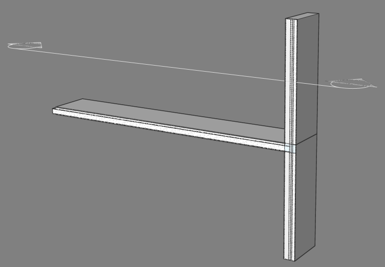
Parametrize and edit a wall-slab connection detail
- To open the DWG file of the detail you want to parametrize click on the detail in the Details panel. The View Detail dialog box displays.
- Click Parametrize, or click Open and run BIMPARAMETRIZEDETAIL. The detail DWG file will open and the detail will be parametrized.
- Open the Mechanical Browser panel.
- Click the Mechanical Browser button in the tool panel set.

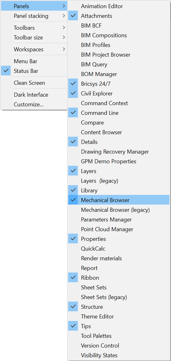
- If the Mechanical Browser button isn't visible yet, move the cursor to the toolbar or ribbon panel and right-click. A context menu displays.
Expand the Panels option.
Select Mechanical Browser in the context menu.
- Once you have clicked on the Mechanical Browser button, the Mechanical Browserpanel displays:
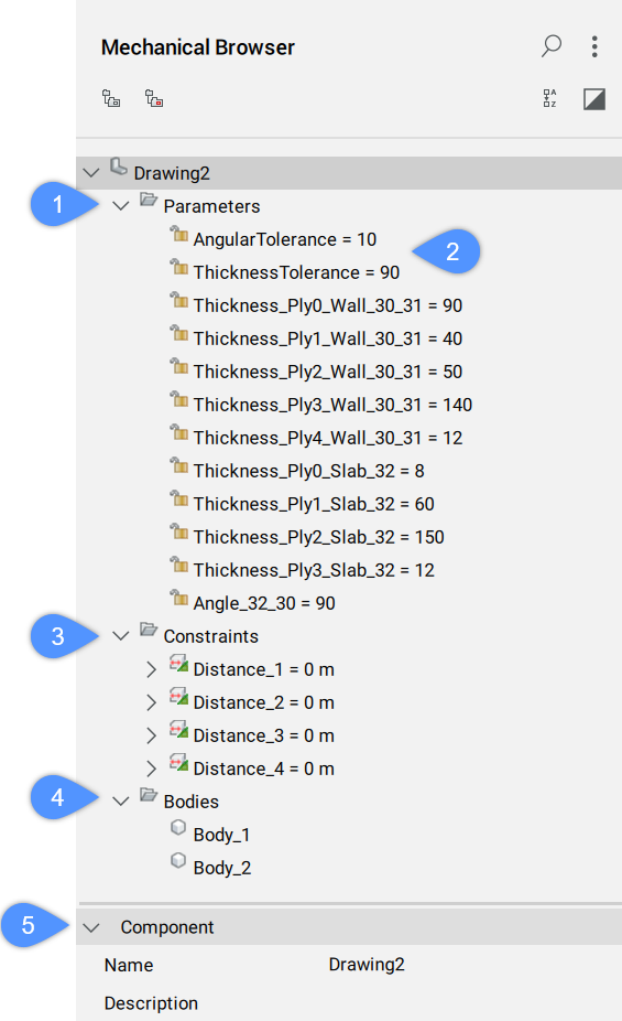
Note: You can also use the MECHANICALBROWSEROPEN command.Parameters (1): Right-click a parameter to open a context menu:
- Geometry-driven: if checked, it makes the parameter geometry-driven.
- Create design table: creates a design table to drive parametric block parameters.
- Animate: animates models by means of parameters.
- Delete: deletes the selected parameter.
- Renumerate similar nodes: renumerates all nodes of the same type and the same level.
- Collapse all: collapse the whole Mechanical Browser.
- Expand all: expand the whole Mechanical Browser.
Tolerance Parameters (2): displays the maximum and minimum variation of an angle, thickness or dimension from the original parameter value.
Constraints (3): contains constraints that you can delete, modify or add.
Note: Some default constraints are generated that link the detail volume and the detail objects to the reference solids. You can delete and replace them with other constraints.Bodies (4): displays the bodies in the model.
Component (5): Displays the properties of the detail file.
- Edit the parameters.
The parameters that were generated have specific values to ensure the detail looks exactly as it was created. If you change these values, the detail will change.
For example:
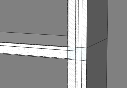
- Change the Thickness_Ply1_Wall_30_31 parameter from 40 to 70 (in the Expression field). The new detail is visibly different in the model space:
Before After 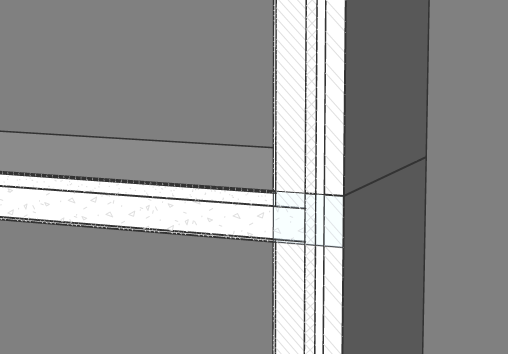
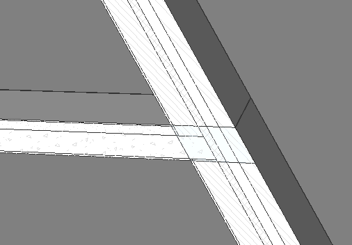
- Change the Angle_32_30 parameter from 90 to 120. The new angle between the wall and the slab is different in the model space.
A warning pops up:

This is because the AngularTolerance parameter was set to 10. The new AngularTolerance parameter automatically changes to 30 because you changed the Angle_30_31 parameter by 30 degrees.
- Click OK
Before After 
- Change the Thickness_Ply1_Wall_30_31 parameter from 40 to 70 (in the Expression field). The new detail is visibly different in the model space:
Parametrize and edit a structural steel connection
- To open the DWG file of the detail you want to parametrize, click on the detail in the Details panel. The View Detail dialog box displays.
- Click Parametrize, or click Open and run BIMPARAMETRIZEDETAIL.
The detail DWG file will open and the detail will be parametrized.
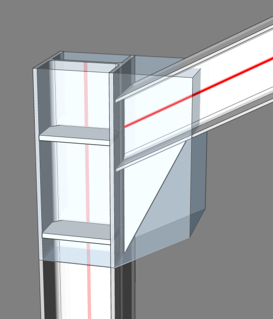
- Open the Mechanical Browser:
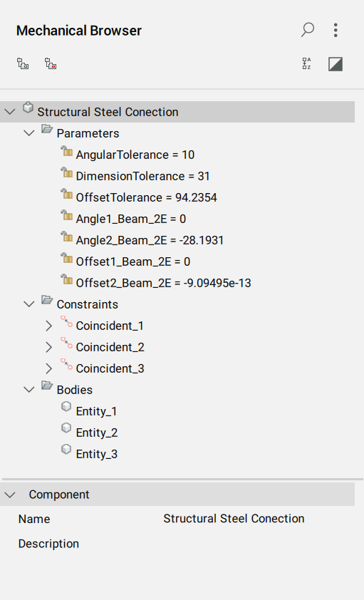
Note: For connections between linear reference solids, only the framework parameters are automatically generated. You must manually add constraints to specify the behavior of detail objects in relation to the reference solids. In this example, three coincidence constraints have been manually added: two to make sure that the connection planes of the triangular steel plate maintain coincident with the flanges of the steel column and girder, and one to make sure that the end section of the girder maintains coincident with the column flange. You can add coincidence constraints before or after the parametrize tool. If you add the coincidence constraints after you can see how the reference solids change with new parameters. This makes it clear which constraints have to be added to make all detail objects move correctly. - Edit parameters.
The parameters that were generated have specific values that make sure the detail looks exactly as it was created. If you change these values, the detail will change.
For example:
- Change the Angle2_Beam_2E from -28.1931013282 to -40. The column and the girder change in the model space.
A warning pops up:

This is because the AngularTolerance parameter was set to 10. The AngularTolerance parameter automatically changed to 11.8069 because you have changed the Angle2_Beam_2E by 11.8069 degrees. Click OK.
Before After 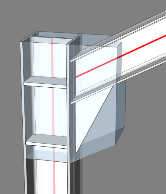
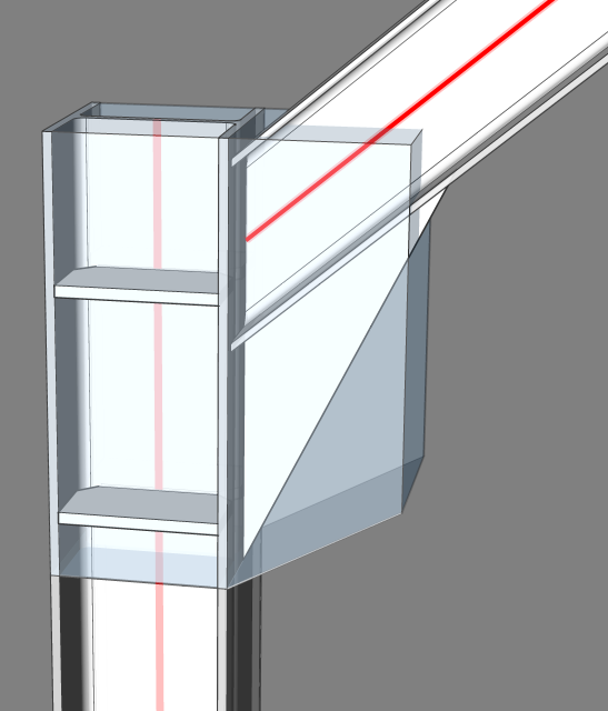
- Change the Offset1_Beam_2E from 0 to 200. You see the girder moves 200 mm downwards.
A warning pops up:

This is because the OffsetTolerance parameter was set to 31. The OffsetTolerance parameter automatically changed to 200 because you changed the Offset1_Beam_2E parameter by 200 mm. Click OK.
Before After 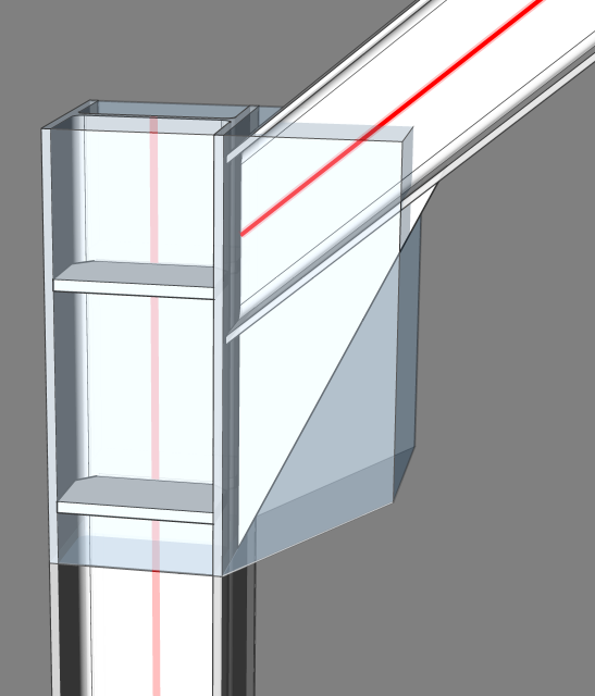
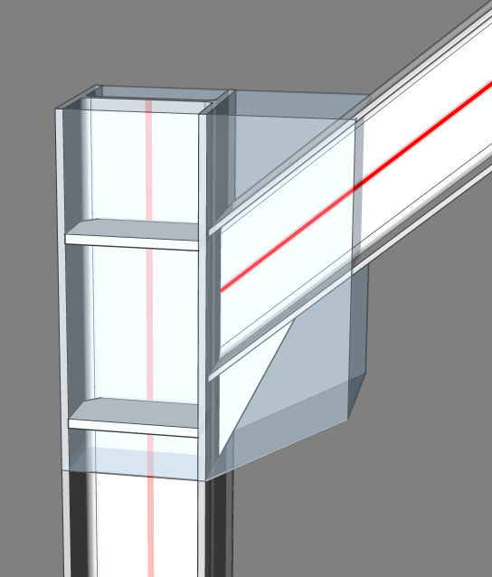
- Change the Angle2_Beam_2E from -28.1931013282 to -40. The column and the girder change in the model space.
Propagate a detail in a project
There are different methods to propagate a detail:
- With the Details Panel: propagate a detail from the project on all similar connections in the project.
- With the BIMPROPAGATEFROMFILE command: propagate a detail from a file.
Fewer suggestions are given by the BIMPROPAGATE command for a detail that is not parametrized. This is because a detail that is not parametrized has fewer possible locations.
For example: if a non-parametrized detail of a wall-slab connection is propagated, BricsCAD BIM won't be able to propagate this detail to a wall-slab connection when the composition is different or a particular ply in the wall differs 10 mm from the corresponding ply in the wall of the original detail. To solve this problem parametrize the detail.
The BIMPROPAGATE command can adapt a detail with parameters to situations that differ from the original (for example: another corner, a smaller profile, etc.). You can decide how much the connections can differ from the original with the tolerance parameters.
Different tolerance parameters:
- Angular: Sets the tolerance on angle parameters of the detail in degrees. Angles in the target situation cannot deviate more than this tolerance value from the original angles in the detail.
- Dimension: Sets the tolerance for the profile dimensions of linear reference solids in the detail. Profile widths and heights in the target situation cannot deviate more than this tolerance from the original widths and heights in the detail.
- Offset: Sets the tolerance for offset parameters of the detail. Offsets in the target situation cannot deviate more than this tolerance from the original offsets in the detail.
- Thickness: Sets the tolerance for the total thickness of planar reference solids in the detail. Thicknesses in the target situation cannot deviate more than this tolerance from the original thicknesses in the detail.
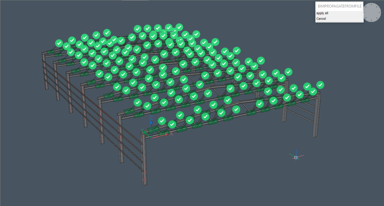
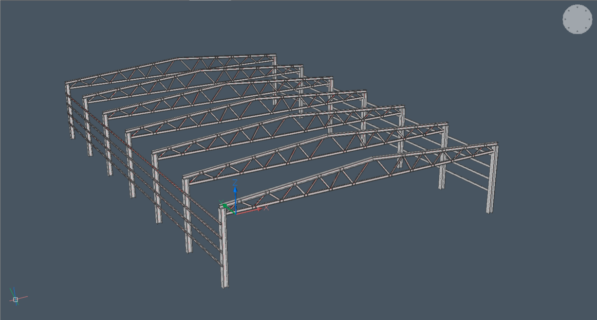
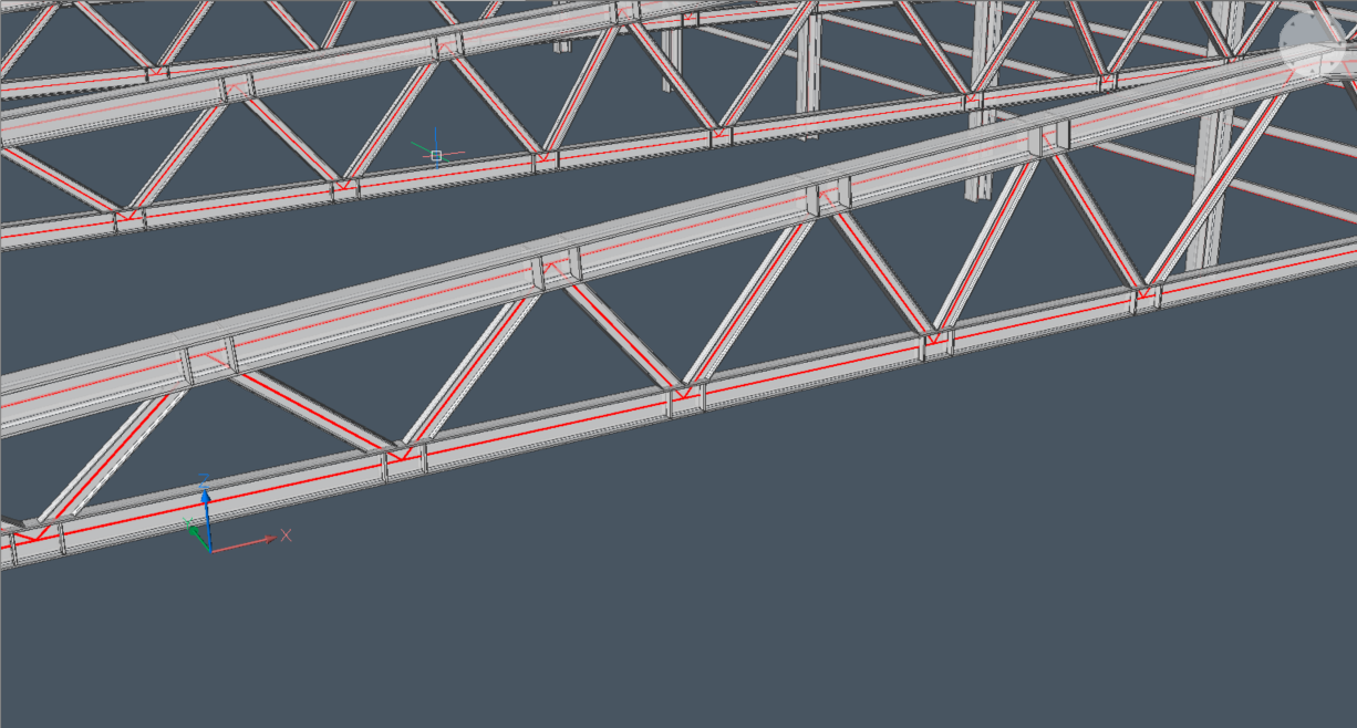
In the following project, there are a lot of similar connections present. However, the angles of the connections vary and the lower beam in the truss and has a different profile size than the upper beam.
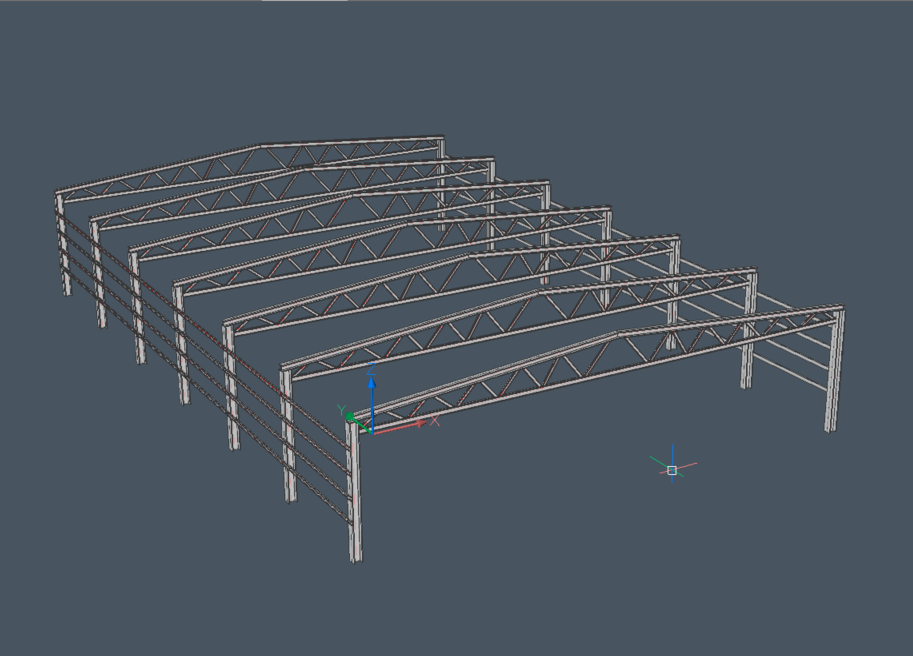
Propagate a detail in the project:
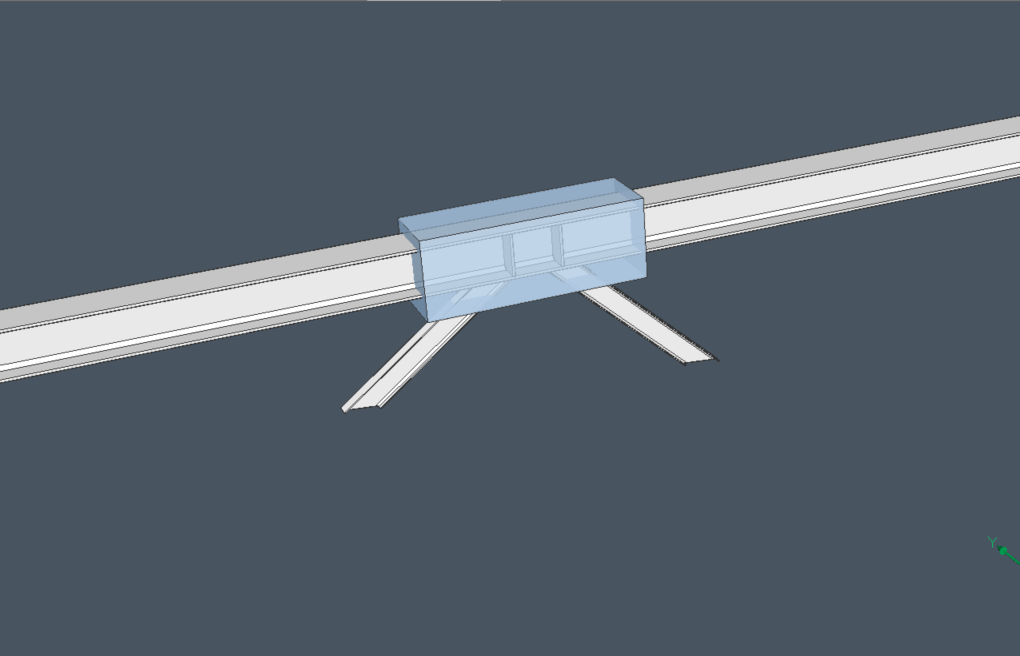
The Mechanical Browser panel displays the parameters. The AngularTolerance parameter is set to 0 degrees, the detail will only propagate to connections with exactly the same angle.
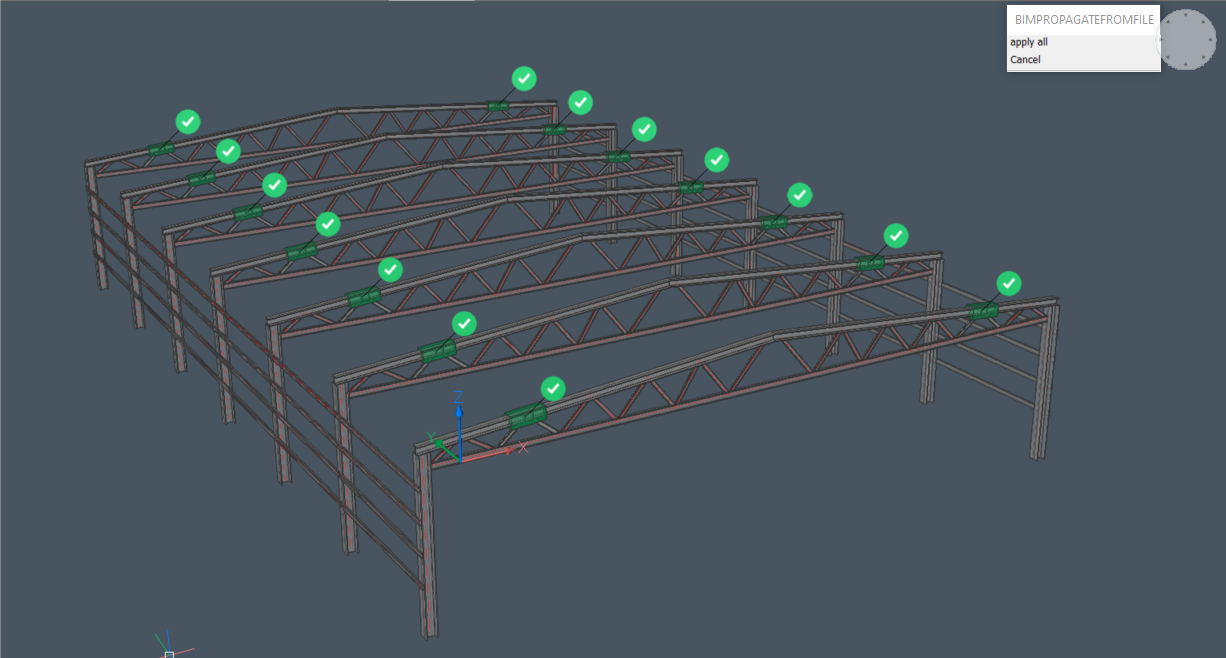
Change the AngularTolerance parameter to 45 degrees. The detail will propagate to all the similar connections. This is because none of the connections exceed the tolerance value.
