Create drawing types with drawing customization
About drawing customizing
BricsCAD BIM uses drawing templates to customize your generated drawings. For a general understanding of how these templates are created and work, please visit the Templates for generated drawings article.
In V21, Drawing Customization allows you to create bespoke templates for drawing types based on a set filter parameter rule against an entity type’s value or property within the 3D BIM model. This is especially helpful for customizing graphics of model entities independent of their assigned layers or layer states, therefore transferable and usable on other projects with similar entity properties.
Drawing customizations panel
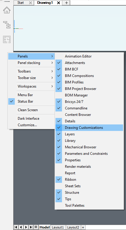
- Right-click the panel and hover to Panels.
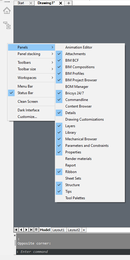
- Select Drawing Customization to dock the tool icon in
the panel.
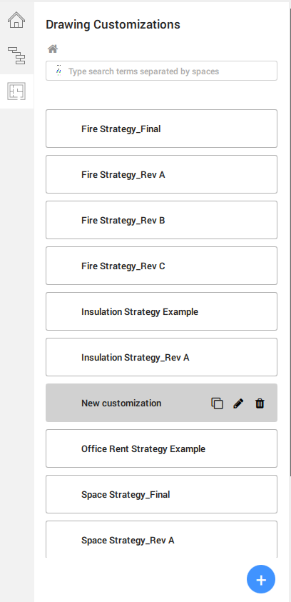
- Open the panel, it allows you to create view templates to control and
customize the visibility settings of your drawings on layouts.
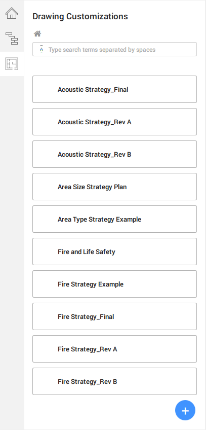
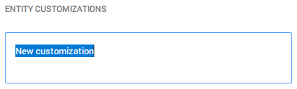
- Click
 to create a
new template. By default, the template is named New
Customization with the text highlighted.
to create a
new template. By default, the template is named New
Customization with the text highlighted.
Note: All the controls of Drawing Customizations are represented as graphic icons within the User Interface panel, such as to
create a new control item. They are repeated throughout the tool in
different settings, for example Entity
Customizations, Ply
Customizations..., but their functions and purposes
remain consistent. - Rename the template whilst the text is being highlighted. Once done, press
Enter to save and apply the name.
Note: You can duplicate, rename or delete your customization templates. - Click the newly created Drawing Customization
template tab to begin defining its customization
settings.The first step into the template brings you to Entity Customizations, where you will create the necessary entity customizations template and will be first described later in this article.
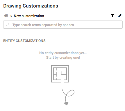
You will also notice a funnel icon and a pencil icon on the top right part of the panel. They are the Filter Rules and Styles tabs respectively.
The 3 principles – Entity Customizations, Filter Rules & Styles – which make up the Drawing Customization tool as described earlier in the article, are now accessible on this main page.
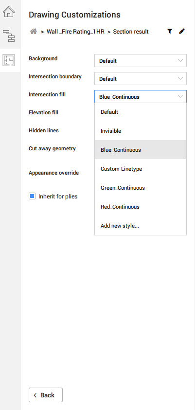
Drawing customizations styles
- Click the pencil icon to access the Styles tab.
This is where your desired style options, such as line weight, line colors..., are stored and will appear as drop-down options in the Entity Customizations and Center Customizations settings as shown in the previous section above.
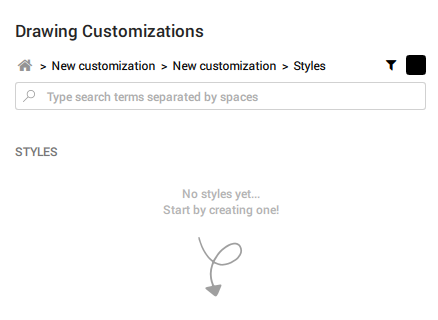
- To create a new style, click at the
bottom right of the panel and a new Style template
tab will appear.
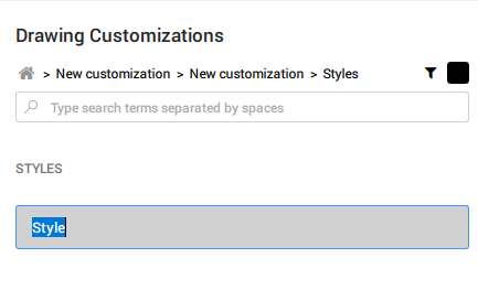
- By default, the tab is named Style. Rename it whilst the text is being highlighted as shown. After you are done, hit Enter to save and apply.
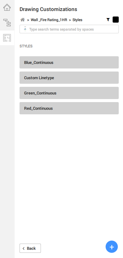
- Create a list of desired styles that you wish to use in this
Drawing Customization template. Each tab contains
its individual styles settings, such as the style’s color, line type, line
weight and line type scale.An example of the style pages a list of templates:
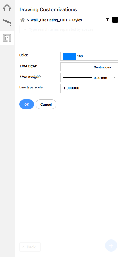
- To edit any of the styles template available, click on its relevant tab to
access its settings.Note: Similar to the Drawing Customization template tabs, hover over the styles template tabs to reveal the function icons to duplicate, rename or delete.Style settings include the options to define Color, Line Type, Line Weight and Line type scale in their respective drop-down dialogs. Once done, click OK to save and apply the changes.
- To leave the Styles page, click
Back at the bottom left side of the panel to
return to your previous page. From there, you can navigate to modify the
Entity Customizations or
Rules templates.Or click on your desired branch in the tree structure map above the search bar to navigate to your desired page.
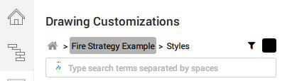
Note: The tree structure map is helpful to keep yourself orientated within the Drawing Customization tool. Similarly, the search bar allows you to narrow to a specific template if you have a long list of values to navigate through.
Entity customizations
- Click .
- To create a new Entity customization template. By
default, the template is named New Customization
with the text highlighted.
- Rename it whilst the text is being highlighted as shown. After you are
done, hit Enter to save and apply.
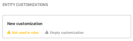
As the Entity customization was newly created and not fully set up, you will find the relevant notices at the bottom of the Entity customization tab. This is a helpful mechanism to remind you if any customization settings have not been defined yet, saving you the need to check the settings manually.
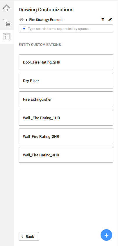
- Create a list of templates for the entities you wish to customize.A list of Entity Customizations templates could look like this:
- After creating your desired Entity customization
templates, click onto the individual tabs to modify their respective
settings.You can choose how the element should look like as a section result, or how a centerline type representation should appear, or how an external symbol representation should replace the original entity.
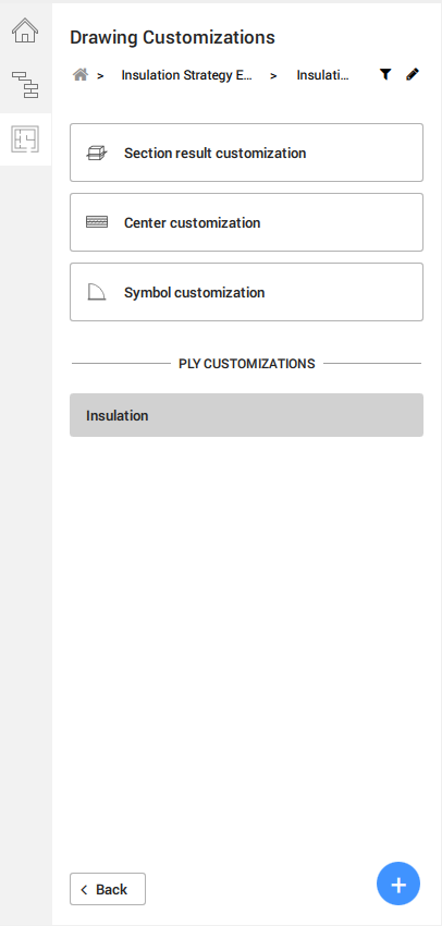
You can further modify and customize a specific ply layer of your desired entity composition, but only if appropriate, e.g. a Wall, Slab or Roof entity.
- The Section result customization displays a
series of controls with drop-down values from the
Styles tab for more specific control of the
section result graphics. You can override the entities’ hatches via the
Appearance Override with pre-set or custom
Physical Materials available in your
project.
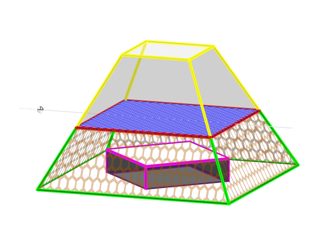
The diagram above illustrates how you could control the visibility and customization settings of an entity with the Drawing Customization tool. Notice that the section plane is aligned with the blue square with red outline.- The green outline represents Background, which is essentially the elevation outline of the cut object.
- The red outline represents Intersection Boundary, which traces over the cut area.
- The blue hatch represents Intersection Fill, as it shows the area of being cut by the section plane.
- The orange hexagons hatch represents Elevation Fill, which refers to the area bound by the elevation outline (see Background).
- The pink outline represents Hidden Lines, as it is below the blue hatch.
- The yellow outline represents Cut away geometry, as it is above the section plane.
Appearance Override allows you to specify how an entity's hatch appearances (section and elevation) would appear, in place of the default hatch patterns already defined within the Physical Materials library. When you create any new Physical Material entry in the In Project category as part of the Drawing Customizationtemplate, your desired configurations are independent of the drawing project and stored in the template instead. You can later apply this template to other project models as you wish.
You can further ensure the customization applies to the plies within the entity composition, if appropriate, by checking the Inherit for plies box.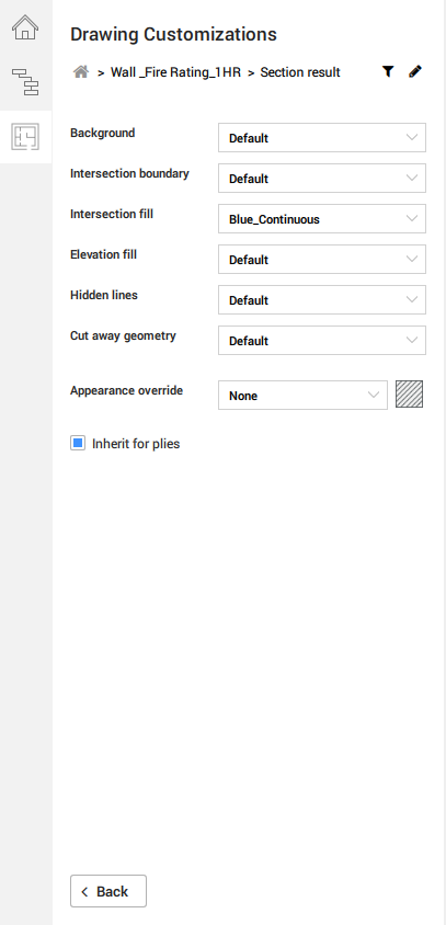
- A similar setup can be found in the Center
Customization settings, where your values in the
Styles section of the customization template
determines the drop-down selections.
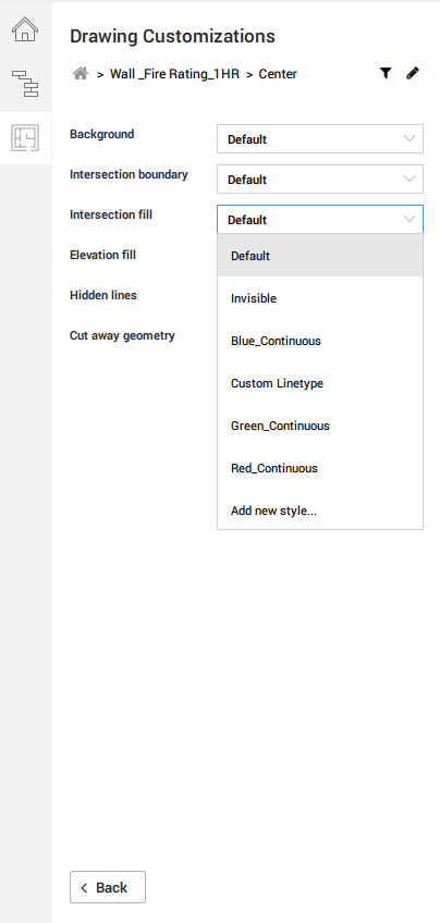
Center customization is particularly useful in scenarios where you would like to display the center elements of various planar and/or linear entities. For example, if you were to apply the center customization settings against a planar entity, e.g. a wall, you would be referring to the display behavior of its center plane. However, if you were to apply the same settings against a linear entity, e.g. a beam, you would be adjusting how the beam's center line appears on the sheet.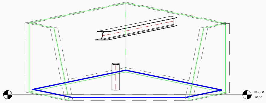
The diagram above illustrates an example of how the center elements differ between planar (wall center plane highlighted in green; slab center plane highlighted in blue) and linear entities (both column and beam center lines in dashed red lines).
There is no default setting to adjust the visibility of these center elements, and they are not normally displayed in section results.
- For the Symbol Customization settings, you can
find an input dialog to specify your desired external symbol drawing in
.dwg format. If you would like to make any further changes to the 2D
geometry itself, you can use the Edit button once
the dialog is referring to your desired symbol drawing.
Alternatively, you can begin creating one on a default symbol template by hitting the Create New button below the dialog.
You can further apply your saved Styles to specific layers within your external symbol source, thereby allowing you to retain a general symbol drawing across several customization templates with different output results.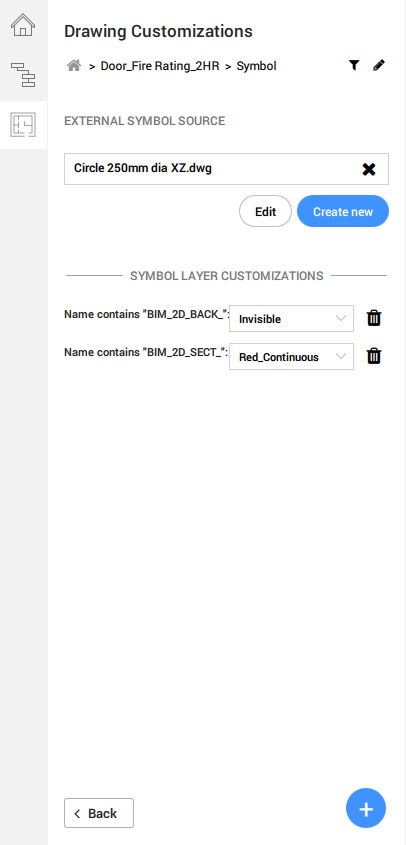
You could also choose not to specify any External Symbol Source, if you already have your desired 2D layers inside the model, usually as a 2D graphical representation that comes alongside the 3D geometry of a Component.
In this instance, simply add a new symbol layer customization value containing part of the desired layer name. If they are part of the default BRX_2D layers, adding "BRX" as a name value will suffice. Drawing Customization will now search within the component entity that the customization template is applied to. This method, however, will not allow any exchanging or sharing of 2D symbols across entities, e.g. replacing a Column with a symbol derived from a BRX layer stored within a (table) Furnishing Element.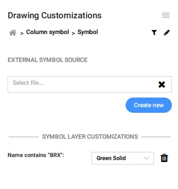
For more information on how BRX layers operate, please visit the chapter Procedure: Understanding the BRX_2D layers in the Templates for generated drawings article.
Filter rules
 on the top
right-hand part of the panel next to the Styles icon.
on the top
right-hand part of the panel next to the Styles icon.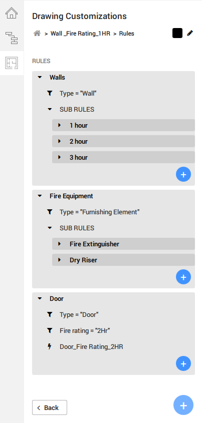
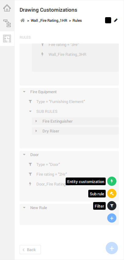
- Filter rules can be further classed into sub
rules, which falls as a sub-set of the parent rule, e.g.
Fire Equipment as a Filter
Rule, whereas Fire Extinguisher is
classed as a sub rule. also
appears respectively and accordingly at each rule level. At the end of each
rule, regardless of it being a subset or otherwise, it has to end with an
Entity Customization.
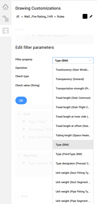
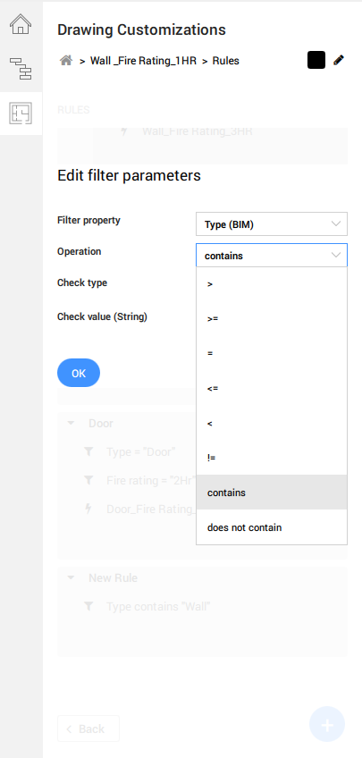
- Adding and editing a filter parameter will lead you to a prompt, where the
options of filter property are determined by the BIMPROPERTIES imported in the
namespace settings.
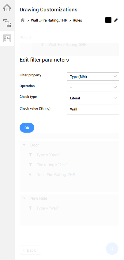
- The filter Operation values are also available as a
drop-down list.Note: You can also start typing a certain keyword to search a specific property that you want to filter on.
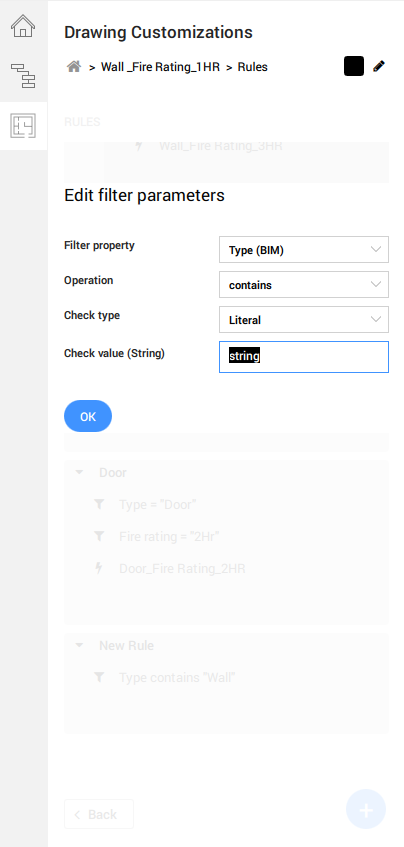
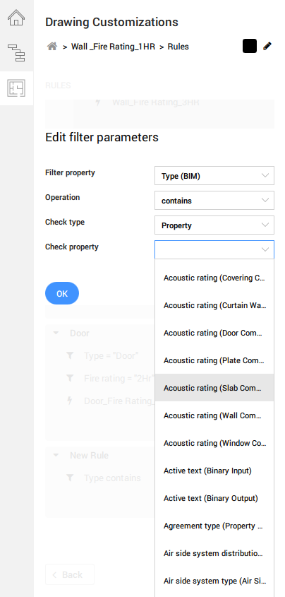
- You can specify a string manually in your check value if your
Check Type is a Literal. If
you have selected a Property value for Check
Type, your Check Property value will
refer to the same values found in the Filter Property
drop-down.
- To end and legitimize a filter rule, the
Entity Customization value must be added and filled
in. The options available in the drop-down selection reflects the existing
customizations tab available in the Entity Customizationpage.
Applying templates to viewports on sheets
- To apply the template, navigate to your sheet drawing with your desired viewport.
- Open the Properties panel and select the viewport to view its
properties.
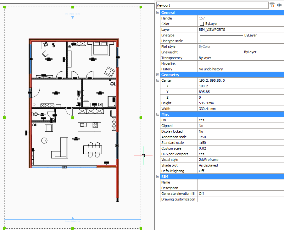
- Navigate to the Drawing Customization property and
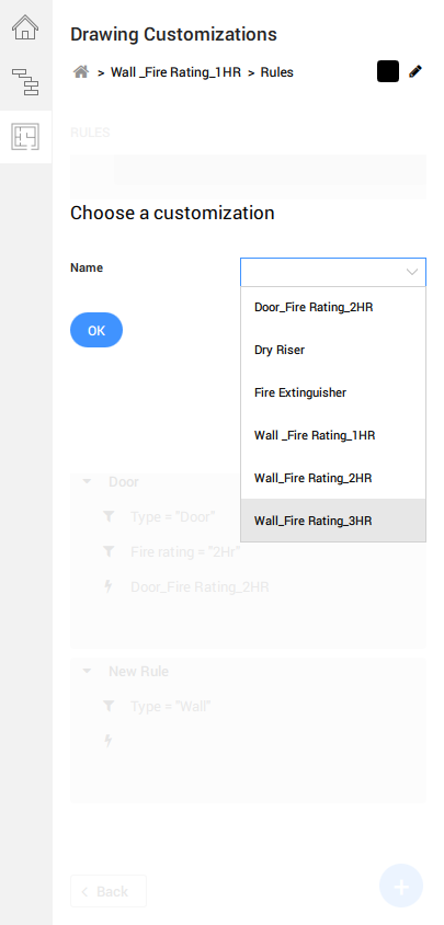
click on the drop-down selection to the right.
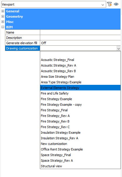
- Select your desired Drawing Customization template.
- Once done, hover over your selected viewport to access the Quad. Click
Update Section in the Quad under
Model tab.
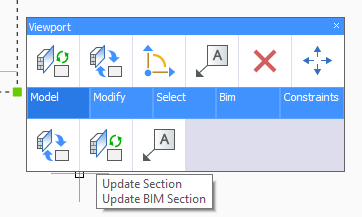
- You should see a refreshed Viewport with the graphical changes as per your Drawing Customization settings.
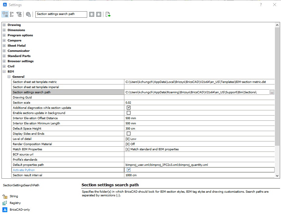
Accessing customization templates
By default settings, these templates are stored in the Customizations folder within your Support folder in the following path, under the Bim folder and then Sections subfolder:
C:\Users\<user_name>\AppData\Roaming\Bricsys\BricsCAD\V21x64\en_US\Support\Bim\Sections\Customizations
The AppData folder is hidden by default, so you may have to unhide it first. This path can also be accessed by entering SUPPORTFOLDER in the Command line.
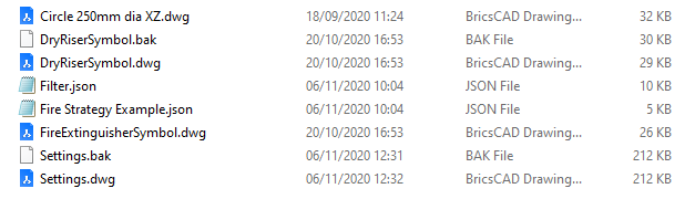
New customizations created with the panel will be stored in a Customizations subfolder in the specified path. Each customization template is saved as an individual folder which contains in its basic form Settings.dwg, a Filter.json and a New customization.json files. The folder will also contain any external symbol sources which you have created new using the Create New buttons.