Templates for generated drawings
About
BricsCAD® BIM contains a series of templates to customize your generated drawings. These templates are stored in your Support folder in the following path:
C:\Users\<user_name>\AppData\Roaming\Bricsys\BricsCAD\V23x64\en_US\Support\Bim\Sections.
The Appdata folder is a hidden folder by default, you may have to unhide folders first. This path can also be accessed with the SUPPORTFOLDER command.
To understand how it works, you must know how BricsCAD® creates layers, hatches, tags, and call-out blocks.
Understanding the created layers
- Open a millimeter template BIM-mm.dwt and save the drawing.
- Draw two boxes of 500x500x400, one a bit behind the other.
- Put the first box on the layer Layer1 (with layer color green) and the second box on the layer Layer2 (with layer color red).
- Create a BIM section, aligned with the front face of the first, green box and cutting through it in the middle, but not cutting through the second, red box.
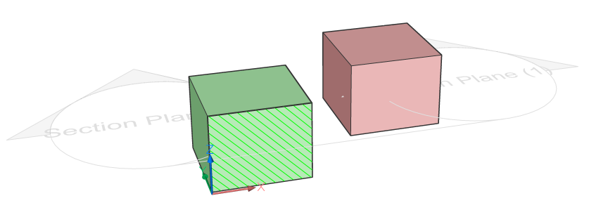
- Generate and open the section drawing.

- Take a look at the Layers panel: three groups of layers have been created: Background, Boundary, and Fill.
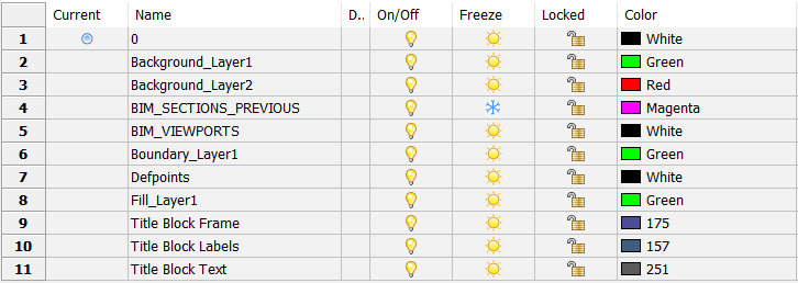
- The generated layers for the green solid are:
- Boundary_Layer1: the boundary of the section through the box.
- Fill_Layer1: the hatching of the section.
- Background_Layer1: shows subentities (e.g., vertices of solids) that are not sectioned.
- The layers all inherit the color of the Layer1 layer.
- Since the red solid is not sectioned, only the Background_Layer2 layer is created. It inherits the color of the Layer2 layer.
- Drag the Cavity Wall, Brick composition from the Compositions panel onto the green box.Note: Set the LEVELOFDETAIL system variable to 1 or 2, to display the ply materials.Note: The composition always gets priority when it is assigned to a solid that is placed on a colored layer. This means that the colors set by default for that composition's layers have priority, not the color assigned to the solid's layer.
- Double-click the Cavity Wall, Brick composition in the Compositions panel.
This composition consists of 4 plies, each with its own material. A physical material is associated with a hatch pattern, used for floor plans and sections. Another pattern is specified for elevations.
- Assign the Concrete, Reinforced composition to the red box.
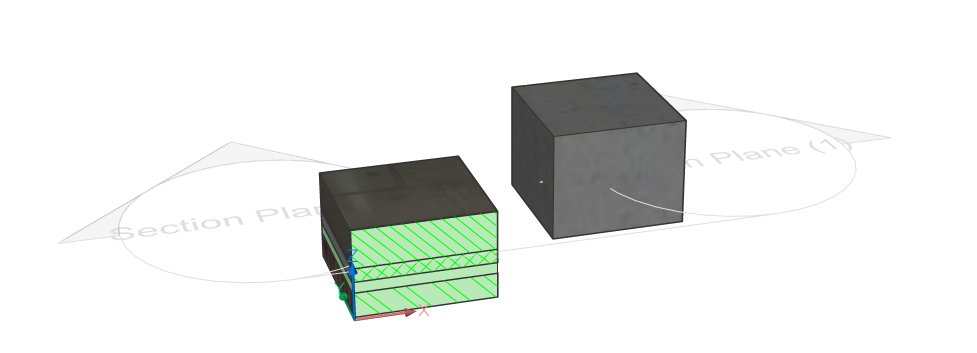
- Update and open the section.

- Go to your layers and execute the PURGE command to remove the unused layers.
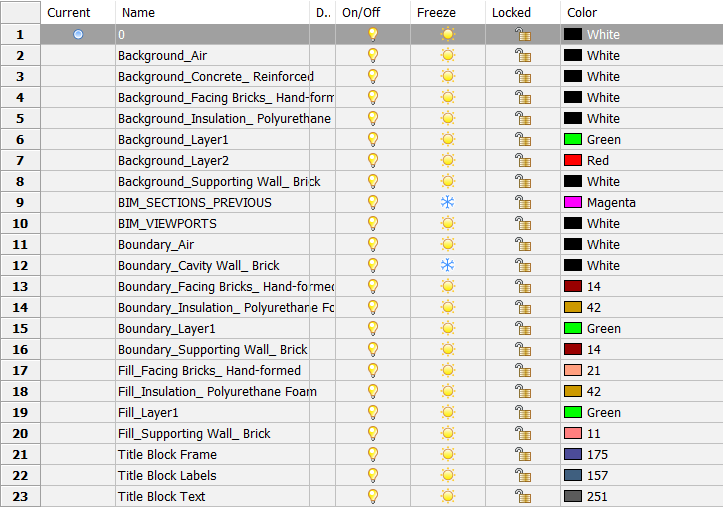
You see the three categories (Background, Boundary, and Fill) again. The second part of the layer name is the name of the physical material used in the solid, instead of the layer name of the box:
- Background_Facing Bricks_Hand-formed, Background_Insulation_Polyurethane Foam, and Background_Supporting Wall_Brick.
- Boundary_Facing Bricks_Hand-formed, Boundary_Insulation_Polyurethane Foam, and Boundary_Supporting Wall_Brick.
- Fill_Facing Bricks_Hand-formed, Fill_Insulation_Polyurethane Foam, and Fill_Supporting Wall_Brick.
- Set the Generate elevation fill property of the section ON to add an elevation hatch.
- Update the section.
- The outline of the second box is now hatched and the layer Elevation_Concrete_Reinforced is added.
Understanding the BRX_2D layers
The 2D symbols will either replace the actual 3D Solid section of the component or be added to the 3D Solid section, depending on their layer:
- Symbols on a layer with prefix BRX_2D_ or BRX_2D+_ will be added to the section block:
- Without being processed by analytical hidden line removal (HLR) when the section plane intersects the components.
It is not possible to have this geometry occluded by some other geometry. E.g. you have a table and chairs. Both have a 2D symbol, but the table is below the section plane and the chairs are cut by it (back rest is higher than table). Then it is not possible to have the table top (BRX_2D_ of table) hide parts of the chairs underneath.
- After going through analytical hidden line removal (HLR) procedure when the section plane does not intersect the components.
- Without being processed by analytical hidden line removal (HLR) when the section plane intersects the components.
- Symbols on a layer with prefix BIM_2D_SECT_ or BIM_2D_SECT+_ will be added only when the section plane intersects the components. All geometry goes through analytical hidden line removal (HLR) procedure. Can be used to have a different representation of the component when it is sliced, e.g. for stairs.
- Symbols on a layer with prefix BIM_2D_BACK_ or BIM_2D_BACK+_ always will be added and all geometry goes through analytical hidden line removal (HLR) procedure. Makes it possible to solve the table-chair problem mentioned above.
- Symbols layers name
- with +: the 2D symbol will be added to the 3D solid section of the component.
- without +: the 2D symbols will replace the actual 3D Solid section of the component.
Adding 2D entities
- Open a millimeter template BIM-mm.dwt and save the drawing.
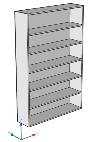
- Drag the component Furniture Bookshelf into the drawing. You can find the component in the Furnishing Elements category in the Library panel (LIBRARYPANELOPEN command).
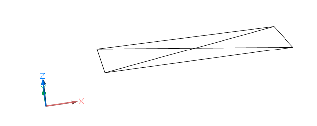
- If you now show and isolate the BRX_2D_Symbols layer, you will see a symbol drawn at the insertion point of the bookshelf.
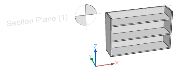
- Show all layers again (LAYUNISO command) and make a section through the bookshelf.
- Generate and open the Plans drawing.

- You will see (if the Boundary_BRX_2D_Symbols layer is on) that only the symbol is drawn onto the plan, and not the real section. It happens because this component had a 2D symbol on the BRX_2D layer attached to it.
- Now return to your 3D model and Open a copy of the bookshelf.
- Hide the bookshelf itself and make sure the BRX_2D_Symbols layer is on.
- Delete one of the lines (of the cross).
- (Optional) Draw extra 2D lines on the BRX_2D_Symbols layer.
- Save the drawing.
- Go back to the original 3D model and type in BMINSERT in the Command line and go to the file path where you just saved the new bookshelf. Click OK and choose a point to insert the bookshelf.
- Regenerate the section and open it. Widen the viewport if necessary, by dragging the existing viewport.

- The second bookshelf has the adapted symbol displayed.
- Draw a wall in your 3D model and insert the door Door Ext Plain into this wall.
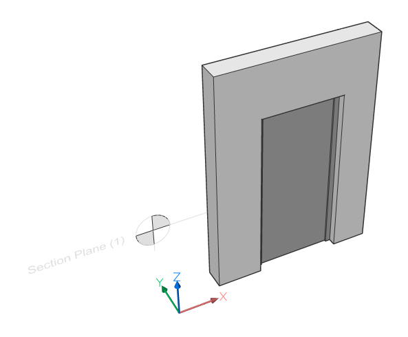
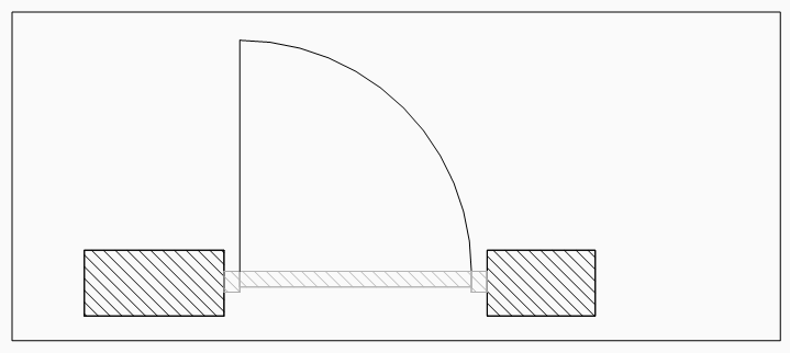
- Repeat steps 3 to 5 but now use the BRX_2D+_Swing layer instead of the BRX_2D_Symbols layer.
- The generated plan displays the symbol of the door swing as well as the door section itself. The BRX_2D+ layer of a component makes sure you can show the real section together with a symbol.
- Symbols on a layer with prefix BRX_2D_ will be used to replace the geometry resulting from the actual section.
- Symbols on a layer with prefix BRX_2D+_ will be added to the section result. Only those 2D entities in a plane parallel to the section plane are.
Customizing the colors and line weights of hatch patterns and lines
- In the above procedure Understanding the created layers, you saw that for objects without a composition, the colors and line weights of the Fill_, Background_, and Boundary_ layers are copied from the layer properties in the 3D model.
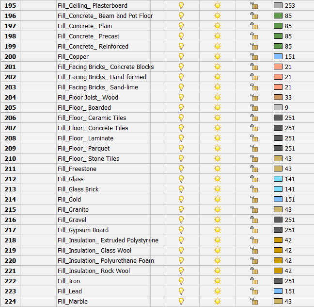
- However, for objects with a composition, the default colors are set by a template found by typing in SUPPORTFOLDER command and browsing to Bim/Sections/_SectionSettings.dwg.
- Open this drawing.
- Go to the Layers panel, you will find a list of all the possible layers that can be created for every material present in the material library. They all have a color and line weight. Changing the color or line weight and saving the file will change the default color/line weight for this layer in your future generated drawings. You can fully customize how your drawing will look for every type of line (Fill, Background, Boundary, or Elevation) per material.
Customizing the hatch patterns
- Open the drawing made in the above procedure 'Understanding the created layers'.
- Open the Compositions panel.
- Double-click the composition Cavity Wall, Brick.
- In the procedure Understanding the created layers, it was stated that you can change the hatch patterns of the materials here. How you need to do this will follow in the next steps.
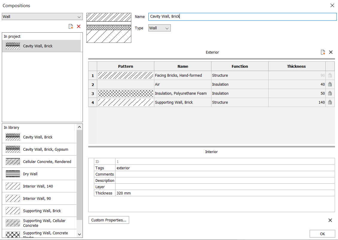
- Double-click on the row of Facing Bricks, Hand-formed. The Physical Materials dialog will pop-up on the material Facing Bricks, Hand-formed. You could have entered this dialog box by typing in the command BLMATERIALS, after which you could have selected the Facing Bricks, Hand-formed material.
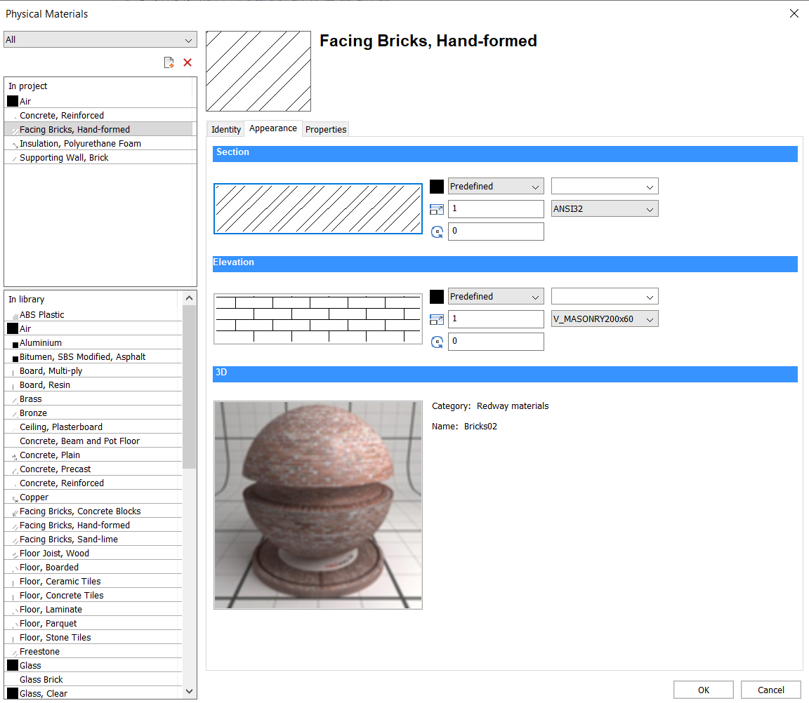
- Go to the tab Appearance.
- Under the title Section, double-click on the hatch pattern.
- Choose your new standard section hatch representation for this particular material. In every composition with this material, the same hatch representation will be used.
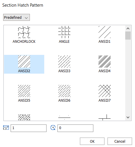
- If you want to change the appearance of an elevation hatch, you can do so by double-clicking the hatch pattern under the Elevation title. The outer most visible material of a composition will be used to determine the elevation hatch.
- Note that the representation of these hatches will not be copied into new drawings as the Physical Materials dialog is not a template, but rather a way to define the representation in a specific drawing.
If you would like to store this information, it is recommended to create a library of compositions. The best way to do so is to make a drawing where you attach the compositions you would like to store to little cubes. Make sure each composition has the hatch appearance you want by going through the process described above.
- Once this is finished, type in BIMPROJECTINFO in the Command line. You will enter the BIM Project Info dialog box.
- In the Project DB tab, switch the value for the database from Embedded to External. You will be asked to save the database on your computer and give it a name, for example, CompositionsTemplate.bsyslib.
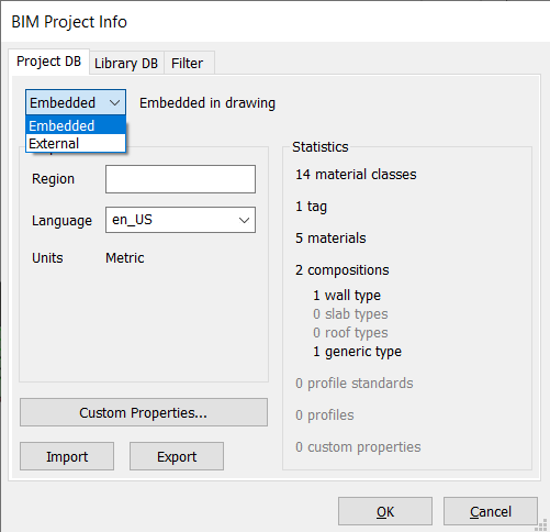
- If you want to use this database (Project DB) in a new drawing, switch the value for the database from Embedded to External. Select the .bsyslib file you created.
Customizing tags per entity type for all section drawings
- Create the source data for a BIM entity type.
- Customize tag blocks.
- Edit the source data to customize BIM Tags for all section drawings.
To change the tags in the current drawing, visit the procedure Customize tag blocks for the current drawing only.
Customizing call-out blocks
- Source files of the various call-out blocks and the section tracker exist in the ..\Support\Bim\Sections subfolder of the Roamable Root folder. By default this is: C:\Users\<user_name>\AppData\Roaming\Bricsys\BricsCAD\Vxx\en_US\Support\Bim\Sections. You can access this file by typing SUPPORTFOLDER in the Command line and browsing to .
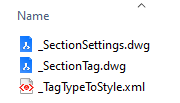
- You can edit _SectionSettings.dwg file to customize the layout of the call-outs and the section tracker blocks.
- When a drawing is generated, the needed call-out blocks are created from the call-out blocks source file. When a BIM section is updated, the existing call-out blocks in the target drawing are used (type BEDIT to choose one to edit).
Customizing the sheet set template
- The sheet set templates are stored in the C:\Users\<user_name>\AppData\Local\Bricsys\BricsCAD\Vxx\en_US\Templates folder.
- If you want to edit an existing template, you have two options. Either you edit it directly, or you make a copy.
- To edit it directly, you can go to Open under the BricsCAD icon, choose .dwt in the Files of type drop-down list and choose the file you want to edit. You can then make the modifications and save the file.
- To make a copy, double-click on the .dwt file you want to copy. A new .dwg with this template will open. Make your modifications and save your file as .dwt. Save it in the templates folder to easily use the copied template in a new drawing.
- If you want to start from scratch, using a wizard, follow the procedure Creating a drawing using a wizard. After the creation and modification of the dwg, save it as a .dwt file in your sheet set templates folder.
- If you have saved the template .dwt to the sheet set templates folder, it appears when you use the New Wizard to open a new drawing. You can select it as the template for creating generated drawings in the sheet set set-up of the Project Browser.
- What can you store in a template?You can make a title block for your template, with sheet set properties, by following the procedure Using sheet set properties in a title block. Do this for every layout in your template. You can also store the following things by using them in your .dwt file:
- Layers
- Colors
- Line types
- Hatch patterns
- Blocks
- Text styles
- Dimension styles
- Page set-ups

