Working with Typed Plans

About Typed Plans
BricsCAD® BIM uses drawing templates to customize your generated drawings. For a general understanding of how these templates are created and work, please visit the Templates for generated drawings article.
Typed Plans allow you to create customized templates for drawing types based on a set filter parameter rule against an entity type’s value or property within the 3D BIM model. This is especially helpful for customizing graphics of model entities independent of their assigned layers or layer states, therefore transferable and usable on other projects with similar entity properties. This makes it easier to ensure adherence to office drawing standards, local government requirements and to achieve consistency across 2D drawings, especially on detailed design and building permit packages.
- At the level of the BIM project.
- In the support folder.
- Typed Plans in a project can be managed in the UI of the BIM Project Browser. It is possible to create a new Typed Plan from the BIM Project Browser, to rename or remove a Typed Plan, or to edit an existing Typed Plan.
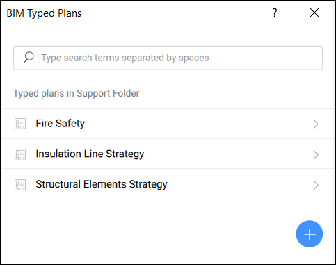
- Typed Plans in the support folder cannot be managed from the BIM Project Browser as they don't belong to a project. Use the TYPEDPLANS command to manage them in the BIM Typed Plans dialog box.
BIM Typed Plans dialog box
-
To open the BIM Typed Plans dialog box, enter the TYPEDPLANS command in the Command line or click on the Typed Plans icon
 in the Ribbon panel.
-
Click
 to create a new template. By default, the template is named New Typed Plan with the text highlighted.
 -
Rename the template while the text is being highlighted. When finished, press Enter to save and apply the name.Note: You can duplicate, delete or rename your typed plans. To do that, hover the cursor over the desired Typed Plan and click the context menu button to expand the options.
-
Edit a Type Plan listed in the dialog box by clicking on its name to open the BIM Typed Plan Editordialog box.
Typed Plans at the level of the Project browser
From the BIM Project Browser panel you can create new Typed Plans or import Typed Plans. To do that, go to the Files tab of the panel and click  at the bottom right of the panel to reveal its options and choose one of the following:
- New Typed Plan
- Creates a new Typed Plan through the BIM Typed Plan Editordialog box.
- Import Typed Plan
- Allows you to import an existing Typed Plan through the Select a Typed Plan to importdialog box. Typed Plans are stored as .tp folders that contain two JSON scripts (one to customize the tags and one to customize the generated drawings) and a Settings.dwg file (stores all the customizations settings referred to in the JSON scripts). You can browse to the location containing the desired .tp folder to be added.
Once created/imported, the typed plan is stored in the BIM project folder, in the subfolder named TypedPlans, and thus accessible through the BIM Project Browser panel's Files tab. Here several options are available by right-clicking on a listed Typed Plan to open the context menu:
- Open Folder
- Opens the folder in the File Explorer of your computer.
- Rename
- Allows you to rename the selected Typed Plan.
- Duplicate
- Duplicates the selected Typed Plan using the default name 'Original Name - Copy'.
- Delete
- Deletes the selected Typed Plan from the project.
To edit one of the Typed Plan in the list, double-click the desired Typed Plan. This opens the BIM Typed Plan Editor dialog box.
Editing Typed Plans
The BIM Typed Plan Editor dialog box allows you to edit the customizations of the selected Typed Plan.
The first step in the template brings you to the definition of the overrides, where you can create overrides to change entity properties to customize the typed plan and add filters. A new override element is added to the list by clicking the Create new override button if no override is already created or Add new override button at the top of the overrides list.
The overrides list functions as a top down filter list. Starting at number one and working down to numbers 2, 3, etc., the list is checked and BricsCAD® BIM determines whether an entity fits any criteria. If the entity falls into one filter, the other filters are no longer verified. Thus, the order in which you place the overrides in the list is very important. It is best to start with the most specific filter lines and then add more broader filter lines. For example you can leave your last filter line so generic to encompass all other elements, by not specifying any filter expression in it.
Drawing overrides refer to the visibility settings of how you would like to have your elements in your model drawing to look like.
There are 4 different types of customizations, which can be specified for each filtered group of elements separately. You can choose how the element should look like as a section result, how a centerline type representation should appear, how an external symbol representation should replace the original entity and you can modify and customize a specific ply layer of your desired entity composition, but only if appropriate, for example a Wall, Slab or Roof entity.
- Section result customization
- Click the context menu button to open the menu options.
- Add customization
- Click the arrow next to Add customization to open the drop-down list with customization types. Click on a type to add it to the Section result customization so you can customize the lines for a more specific control of the section result graphics.
- Center line customization
- Centre Customization determines the appearance of the center of planar or linear entities. The resulting center lines, for example from cutting a wall’s center plane in a floorplan, can be customized.
- Symbol customization
- Click the context menu button to open the menu options.
- Ply Customization
- Can be used to show only a certain type of plies in a plan view. An easy example is the visibility of only structural plies in a structural plan. Click the context menu button to open the menu options.
Drawing customizations styles
Once a customization is added using the steps mentioned before, the styles of selected entity types can be created and customized on the fly. Several characteristics can be specified:
- Visibility
- Sets the visibility of the entity type on or off.
- Color
- Specifies the color of the entity type.
- Linetype
- Specifies the linetype of the entity type.
- Lineweight
- Specifies the lineweight of the entity type.
- Linetype Scale
- Specifies the linetype scale of the entity type.
Applying templates to viewports on sheets
- To apply the template, navigate to your sheet drawing with your desired viewport.
- Open the Properties panel and select the viewport to view its properties.Note: This can be done by using the PROPERTIES command or by clicking the Properties panel icon.
- Navigate to the Typed Plan property under the BIM properties section and click on the drop-down selection to the right to select the desired typed plan.
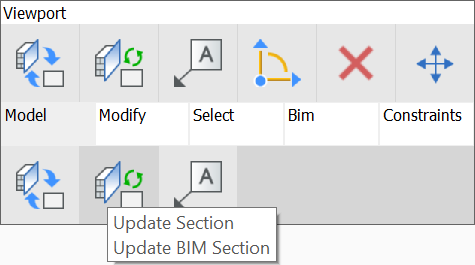
- Once done, hover over your selected viewport to access the Quad. Click Update Section in the Quad under Model tab.
- You should see a refreshed Viewport with the graphical changes as per your Typed Plans settings.
Accessing customization templates
By default settings, these templates are stored in the Customizations folder within your Support folder in the following path, under the Bim folder and then Sections subfolder:
C:\Users\%username%\AppData\Roaming\Bricsys\BricsCAD\V24x64\en_US\Support\Bim\Sections\Customizations
The AppData folder is hidden by default, so you may have to unhide it first. This path can also be accessed by entering SECTIONSETTINGSSEARCHPATH in the Command line.
You can specify a different path if your Customization files are stored elsewhere in an accessible folder. Simply redefine the path in the Section settings search path in the Settings dialog box, or in the Command line.
New customizations created with BIM Typed Plans will be stored in a Customizations subfolder in the specified path. Each customization template is saved as an individual folder which contains in its basic form Settings.dwg, a tag-customization.json and a New drawing-customization.json files. The folder will also contain any external symbol sources which you have created new using the Create New buttons.
Settings.dwg contains the values created in the Customization sections in the Drawing Override tab in the form of layers and if you have created any custom properties that you wish to use as a Filter parameter, you have to ensure they are also reflected in the Settings.dwg.


