
Sheet Metal Global and Feature Properties
About
The Mechanical Browser panel controls global properties and feature-specific settings of sheet metal parts, allowing you to adjust and refine sheet metal behavior.
When working with sheet metal parts, clicking the root node in Mechanical Browser panel, displays the properties of entire drawing. Sometimes these properties are referred to as the global Sheet metal context associated with the drawing, each sheet metal part sharing this context by default.
See the Mechanical Browser for Sheet Metal article for more information on working with sheet metal through the Mechanical Browser panel.
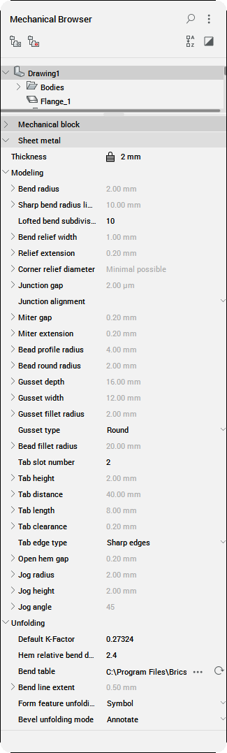
Global Properties
| Global Properties | Description |
|---|---|
| Thickness | Global sheet metal material thickness.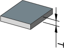
|
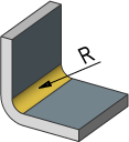
| Bend radius | Default radius of bend features; it can be changed per bend as well.
|
| Sharp bend radius limit | Maximum bend radius to be considered a sharp (regular) bend. Used in the SMCONVERT and SMRELIEFCREATE commands to distinguish between regular and lofted bends.
|
| Lofted bend subdivisions | Sets the default number of subdivisions for unfolded lofted bends. |
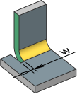
| Bend relief width | Width of the cut near a single bend.
|
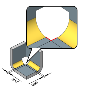
| Relief extension | Size of the bend or corner relief extension.
|
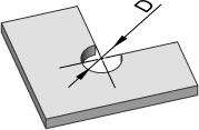
| Corner relief diameter | Default diameter of a circular corner relief. Type: minimal possible or absolute value. 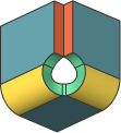
|
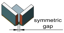
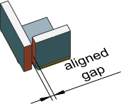
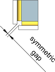
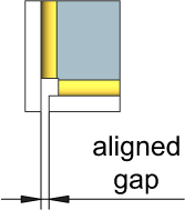
| Junction gap | Gap between 2 adjacent flanges.
|
| Junction alignment | Control the alignment of junction faces with the corresponding corner relief faces.
|
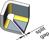
| Miter gap | Gap between the thickness faces of a flange or the adjacent bend when splitting, see SMSPLIT.
|
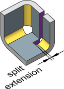
| Miter extension | Control the depth cut of an adjacent flange in case of a flange split.
|
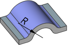
| Bead profile radius | Radius of a tool, which creates the bead.
|
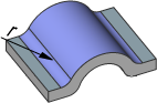
| Bead round radius | Radius of the fillet between the flange and a bead.
|
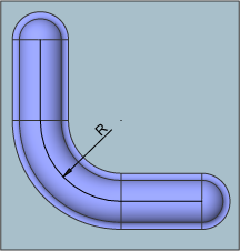
| Bead fillet radius | Radius of the bead control curve filleting. See Working with Form and Bead Features.
|
| Tab slot number | Defines the tab slot number. |
| Tab height | Defines the tab height.
|
| Tab distance | Defines the tab distance.
|
| Tab length | Defines the tab length.
|
| Tab clearance | Defines the tab clearance.
|
| Tab edge type | Controls the tab edge type.
|
| Open hem gap | Defines the hem gap.
|
| Jog radius | Defines the jog radius.
|
| Jog height | Defines the jog height.
|
| Jog angle | Defines the jog angle value. |
| Unfolding | Parameters for the unfolded representation. |
| Default K-Factor | K-Factor for the bend radius equal to the thickness. |
| Hem relative bend deduction | Defines the bend deduction relative to thickness used in hem features unfolding. |
| Bend table | Display the Open dialog for bend tables in CSV file format. |
| Bend line extent | Control how far a bend line extends beyond the unfolding boundary (zero and negative values are allowed).
|
| Form feature unfolding mode | Control the appearance of form features in the unfolded representation.
|
| Bevel unfolding mode | Control the bevel unfolding mode (see Working with Bevels article)
|


Feature Properties
Feature properties display automatically when selecting a feature in the Mechanical Browser panel.
| Feature Properties | Description |
|---|---|
| Common property: Name: the name of the selected sheet metal feature. Optionally type a name for the feature. The default name of a feature is the feature type plus an increment, for example, Flange_1, Flange_2, ... |
|
| Flange feature | Click a flange feature: Thickness: current thickness. The value is read-only; it equals the sheet metal component thickness property. |
| Bend feature | Click a bend feature:
|
| Bend relief | Click a bend relief feature:
|
| Corner relief | Click a corner relief feature:
|
| Junction feature | Click a junction feature:
|
| Miter feature | Click a miter feature:
|
| Form feature | Click a form feature:
|
| Bevel feature | Click a bevel feature:
|
Feature Context Menus
Right-click a feature to display the feature context menu.
| Feature Context Menus | Description |
|---|---|
Common tools:
|
|
| Flange feature | Right-click a flange feature: 
Flip: swap the sides of a selected flange so that the reference face is on the opposite geometric side of the flange. This operation shifts the flange by its thickness, to preserve the position of the reference face. |
| Bend feature | Right-click on a bend feature: 
|
| Lofted Bend feature | Right-click on a lofted bend feature:
|
| Wrong Bend feature | Right-click on a wrong bend feature: 
Repair feature: repair a wrong bend feature by creating a bend feature with proper geometry, if possible. |
| Bend Relief feature | Right click on bend relief feature: 
Switch to smooth/round/rip: switch a bend relief to the selected feature type. |
| Corner relief feature | Right-click on corner relief feature: 
Switch to V-type/circular: switch a corner relief feature to the selected feature type. |
| Junction feature | Right-click on junction feature: 
|
| Miter feature | Right-click on miter feature: 
|
| Form feature | Right-click on form feature: 
|
| Tab feature | Right-click on tab feature: 
|
| T-junction feature | Right-click on T-junction feature: 
Switch to T-tab: convert a T-junction feature to a T-tab feature. |
| T-tab feature | Right-click on T-tab feature:
Switch to T-Junction: convert a T-tab feature to a T-junction feature. |
