Working with sections
The SECTION command creates section planes of 3D solids; the results are region entities.
The SECTIONPLANE command creates a section entity that creates sections of 3D solids, surfaces, and meshes.
The LIVESECTION command toggles the Live Section property of a section plane.
The SECTIONPLANESETTINGS command defines the properties of a section plane entity in the Drawing Explorer - Section Planes dialog box.
You can edit the properties of a selected section plane in the Properties panel.
The SECTIONPLANETOBLOCK command saves the selected section plane to a 2D cross section / elevation block or a 3D cutaway section block.
- The BIMSECTION command creates BIM section entities, which are Section entities with extended properties, such as type (plan, section, elevation) and initial scale of the 2D section result.
- The BIMIFY command can assign BIM properties to a Section entity.
Difference between Live Section and Clip Display
In both statuses all drawing content is sectioned and clipped-away parts are no longer displayed.
With Live Section selected, entities in a drawing are temporarily modified, for example clipped solids are replaced by temporary solids with a different shape.
With Clip Display selected, the display of entities is clipped. Entities are not replaced by temporary versions. You can continue using all modeling and editing operations on all drawing content.
To align a section plane to a face
- Launch the SECTIONPLANE command.
- Choose the select Face option.
- Select the face of a solid you want to align the section plane to.
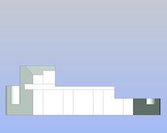
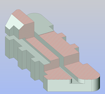
Solid Select face Section plane aligned to face - The section plane is aligned to the selected face.
The Clip Display property of the section entity is switched On automatically.
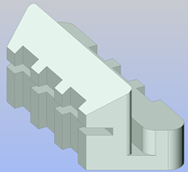
To create a vertical section plane
- Launch the SECTIONPLANE command.
- Specify two points.
The section plane is a vertical plane created through these points.
The part of the solid at the right hand side (with respect to the draw order of the points) of the section plane is cut away.
The Clip Display property of the section entity is switched On automatically.
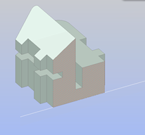
Specify two points Vertical section plane
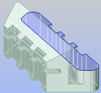
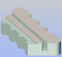
To create a horizontal section plane
- Choose Front in the LookFrom control.
- Align the UCS to the front view by using the View option of the UCS command.Note: If UCSORTHO = On and NAVVCUBEORIENT = 0, the UCS aligns with the view automatically.
- Launch the SECTIONPLANE command.
- Specify two points.
- The section plane is created through these points and perpendicular to the XY-plane of the current coordinate system.
- The part of the solid at the right hand side (with respect to the draw order of the points) of the section plane is cut away.
- The Clip Display property of the section entity is switched On automatically.
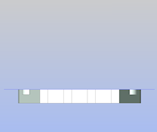
Specify two points The part of the solid at the right hand side of the section plane is cut away Horizontal section plane
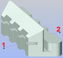
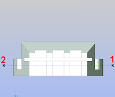
To create a vertical jogged section plane
- Launch SECTIONPLANE command.
- Choose the Draw option.
- Specify the first point (1).
- Specify the second point (2):
- Specify the other points (3 - 6), then right click or press Enter to stop.
- Click a point (7) to specify the direction of the section entity.
The part of the solid opposite to the direction of the section entity is cut away.
The Clip Display property of the section entity is switched On automatically.
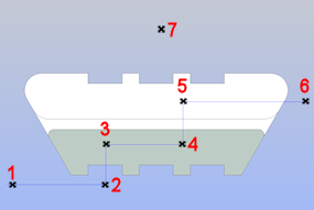
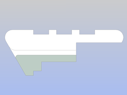
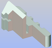
Specify points The part of the solid opposite to the direction of the section entity is cut away Vertical jogged section plane
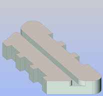
To create a horizontal jogged section plane
- Choose Front in the LookFrom control.
- Align the UCS to the front view by using the View option of the UCS command.Note: If UCSORTHO = ON and NAVVCUBEORIENT = 0, the UCS aligns with the view automatically.
- Launch the SECTIONPLANE command.
- Choose the Draw option.
- Specify the first point (1).
- Specify the second point (2).
- Specify the other points (3 - 6), then right click or press Enter to stop.
- Click a point (7) to specify the direction of the section entity.
The part of the solid opposite to the direction of the section entity is cut away.
The Clip Display property of the section entity is switched On automatically.
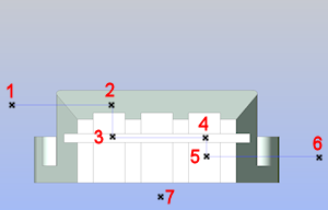
Specify points The part of the solid opposite to the direction of the section entity is cut away Horizontal jogged section plane
To create an orthographic section plane
- Launch the SECTIONPLANE command.
- Choose the Orthographic option.
- Pick the orthographic section orientation of your choice in the prompt menu or type the corresponding option in the Command line.
Orthographic section planes are created through the center of the solid, parallel to the XY-plane (Top and Bottom), YZ-plane (Left and Right) or XZ-plane (Front and Back) of the current coordinate system.
The Clip Display property of the section entity is switched On automatically.
To modify the size and position of a section plane
- Select the section plane entity in the drawing.
Depending on the current type of the section plane entity a number of grips display.
- (Optional) In the Properties panel, switch on the Clip Display property of the section plane to see the result of the modifications dynamically.
- (Optional) Set the Type property to Plane.
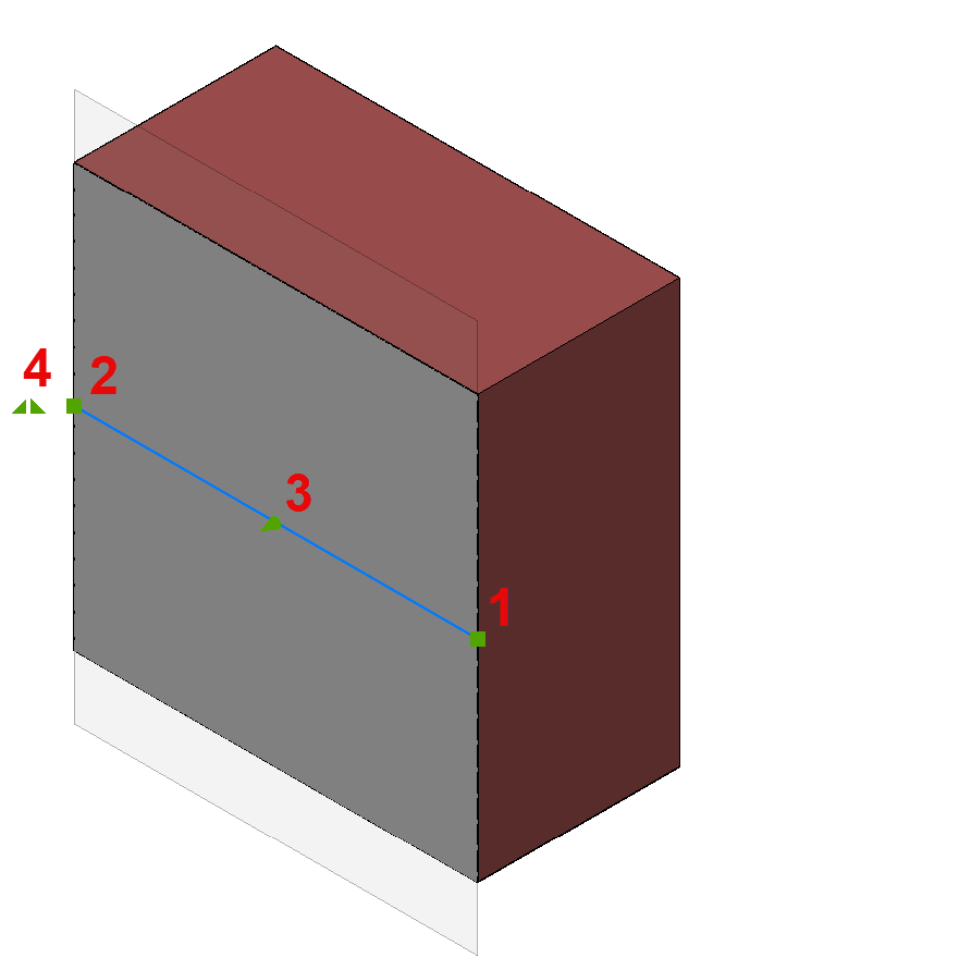
Four grips display.
- 1 (
 ) = origin point: moves the position of the section plane in the XY-plane.
 - 2 () = through point: redefines the through point of the section plane.
The section plane is rotated around the origin point (1).
- 3 (
 ) = midpoint: moves the section plane parallel in a direction perpendicular to the section plane.
 - 4 (
 ): click to flip the view direction of the section plane.
- 1 (
- (Optional) Set the Type property to Boundary.
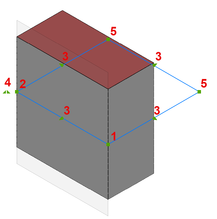
Nine grips display.
- 1 () = origin point: moves the position of the section plane in the XY-plane.
- 2 () = through point: redefines the through point of the section plane.
The section plane boundary is stretched and rotated around the origin point (1).
- 3 (): stretches the section plane boundary parallel.
- 4 (): click to flip the view direction of the section plane.
- 5 (): modifies the shape of the section plane boundary.
- 1 (
- (Optional) Set the Type property to Volume.
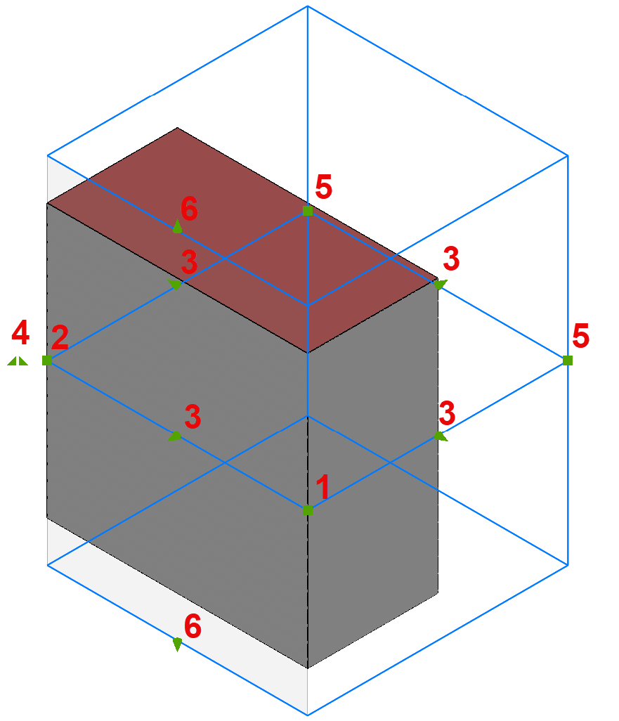
Eleven grips display.
- 1 () = origin point: moves the position of the section plane in the XY-plane.
- 2 () = through point: redefines the through point of the section plane.
The section plane volume is stretched and rotated around the origin point (1).
- 3 (): stretches the section plane volume parallel.
- 4 (): click to flip the view direction of the section plane.
- 5 (): modifies the shape of the section plane volume.
- 6 (): modifies the height of the section plane volume.
Polar Tracking must be turned on to move grip 6.
- 1 (
- (Optional) Set the Type property to Slice.
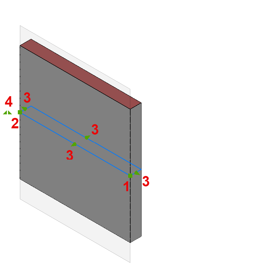
Seven grips display.
- 1 () = origin point: moves the position of the section plane in the XY-plane.
- 2 () = through point: redefines the through point of the section plane.
The section plane is rotated around the origin point (1).
- 3 () = midpoint: moves the section plane parallel in a direction perpendicular to the section plane.
- 4 (): click to flip the view direction of the section plane.
- 1 (
To save a section
The SECTIONPLANETOBLOCK command allows to:
- Insert a section in the drawing as a 2D section or elevation block, or as a 3D cutaway block.
- Replace a section block (for example, when the section entity has been modified).
- Save a section to a new drawing.