SECTIONPLANE command
Creates section entities.

Icon: 
Alias: SPLANE
Description
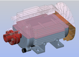
Creates section entities for 3D solids, 3D surfaces, polyface meshes and 3D faces. This command helps you to see inside a 3D entity.
Method
Specify a start point and a through point for the section line, then specify the direction of the section entity. The part of the solid at the right hand side (with respect to the draw order of the points) of the section plane is cut away.
- Use entity snaps to make the pick points accurate.
- Turn on the ORTHOMODE system variable to create a section plane restricted to the X or Y axis.
- Dynamic dimensions are displayed if Dynamic Input (DYN) is set to On (see Dynamic dimensions article).
By default, the command creates a section entity of type Plane with the Clip Display property set to On.
You can set a different type by using the Type option in the Command line or the Type property in the Properties panel.
- Control the visibility of section planes with the SECTIONPLANEVISIBILITY system variable.
- Use the SECTIONPLANESETTINGS command to edit the section entities.
You can also adjust the Section offset and Slice thickness values in the Properties panel using direct numerical input or the spinners. Control the step size of the increments with the SLICETHICKNESSSTEP and SECTIONOFFSETSTEP system variables.
Options within the command
- select Face
- Creates a section plane that coincides with the selected face of a 3D solid.
- Draw
- Draws a polygonal-shaped section entity of the current type, perpendicular to the current UCS. Pick two or more points to define the section line, then specify the direction of the section entity.
- Orthographic
- Places a section plane entity in one of the six standard drawing orientations, relative to the current UCS.
- Type
- Defines the type of section entity to be created.
- Plane
- Sets the section entity type to Plane.
- Boundary
- Sets the section entity type to Boundary.
- Volume
- Sets the section entity type to Volume.
- Slice
- Sets the section entity type to Slice.Note: The Draw option is deactivated for this type.


