Transparent Commands in BricsCAD
Use Civil Transparent Commands to enter a value based on known information (a point, distance, or radius).
You can run the transparent commands within another command (for example, PLINE, 3DPOLY, ALIGNMENT) by using the following methods:
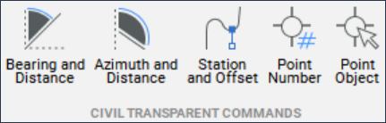
- Click the command in the Civil Transparent Commands ribbon panel in the Home tab of the Ribbon.
- Enter the command at the Command line.
- Activate the Civil Transparent Commands toolbar and select the command.
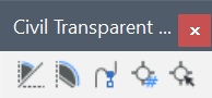
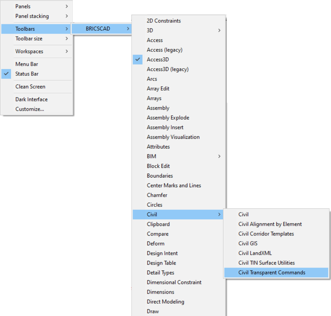
To activate the Civil Transparent Commands toolbar, right-click the ribbon, go to Toolbars, select BRICSCAD, and under Civil, select Civil Transparent Commands.
Bearing and distance 
Alias: 'BD
Specifies a point location at a bearing and distance from a known point. The output is a coordinate of a new point.
Options within the command
- Specify quadrant
- Allows you to select the quadrant needed.
Quadrants: NE = 1, SE = 2, SW = 3, NW = 4
- Specify bearing
- Specifies the angle measured inside the selected quadrant. The measurement is very precise (degrees, minutes, seconds).
You can specify the angle dynamically on the drawing or by typing it in the Command line. (NE: 0, 90: SE: 90, 0: SW: 0, 90: NW: 90, 0 - As an example, for NE, 0 represents the N axis and the starting axis for measurement. The ending axis is represented by 90 degrees and in our example, that is the E axis.)
Or, you can enter the angle in decimal numbers and it will be converted to degrees, minutes and seconds (the first two decimal digits represent minutes and the second two represent seconds).
Note: The valid values are:- for degrees: 0-90
- for minutes: 0-59
- for seconds: 0-59
- Specify distance
- Specifies the offset from the origin of the quadrant at the previously specified angle. You can specify the distance dynamically on the drawing or by typing it in the Command line.
Example: Run the PLINE command:
: PLINE
Select start of polyline or [Follow] <Last point>:
Set next point or [draw Arcs/Distance/Follow/Halfwidth/Width]:
Set next point or [draw Arcs/Distance/Follow/Halfwidth/Width/Undo]: 'BD

>>Specify quadrant [1 for North East, 2 for South East, 3 for South West, 4 for North West]: 1
>>Specify bearing: 40d30'20"
>>Specify distance: 123
Resuming PLINE commandAzimuth and distance 
Alias: 'ZD
Specifies a point location at an azimuth and distance from a known point.
Options within the command
- Specify azimuth
- Allows you to select an angle relative to the line previously created by the command. This can be done dynamically in the drawing or by typing the exact angle in the Command line (degrees, minutes, seconds, or in decimal numbers).
- Specify distance
- Allows you to specify the offset from the starting point. This can be done dynamically or by typing it in the Command line.
Example: Run the PLINE command:
: pl
Select start of polyline or [Follow] <Last point>: 0,0
Set next point or [draw Arcs/Distance/Follow/Halfwidth/Width]: '_ZD
Specify azimuth: 60
Specify distance: 50
Set next point or [draw Arcs/Distance/Follow/Halfwidth/Width]:
Station and offset 
Alias: '_SO
Specifies a point location at a station and an offset from an alignment.
Options within the command
- Select alignment
- Allows you to select the Horizontal Alignment needed to be used.
- Specify station
- Allows you to select any point on the alignment as starting point.
- Specify offset
- Creates a supporting line, perpendicular on the station. This allows you to specify the offset on the supporting line. You can select the distance graphically or by typing it in the Command line.
Example: Run the PLINE command:
: PLINE
Select start of polyline or [Follow] <Last point>:
Set next point or [draw Arcs/Distance/Follow/Halfwidth/Width]:
Set next point or [draw Arcs/Distance/Follow/Halfwidth/Width/Undo]: '_SO


>>Select alignment:
>>Specify station:
>>Specify offset:
Resuming PLINE command
Point number 
Alias: '_PN
Specifies a point location using a point number. You can enter multiple point numbers or number ranges separated by commas.
Example: Run the 3DPOLY command:
: 3DPOLY
Start of polyline: '_PN
>>Enter point number: 1-4
Resuming 3DPOLY command
Point object (selected in drawing graphically) 
Alias: '_PO
Specifies a point location by picking an existing Civil Point.
Example: Run the 3DPOLY command:
: 3DPOLY
Start of polyline: '_PO
>>Select point object:
Resuming 3DPOLY command
>>Select point object:
Resuming 3DPOLY command
>>Select point object:
Resuming 3DPOLY command