Working with the Structure panel
The Structure panel displays a structured tree view of the entire drawing content and enables you to easily work with it (filter, group and sort elements to easily select it and modify their properties).
- Default: displays a layer-based structure.
- Mechanical: displays an entity-based structure.
- BIM: displays a BIM entity-based structure.
- BIM - Compositions: displays a BIM composition-based structure.
- BIM - Profiles: displays a BIM profile-based structure.
- BIM - Types: displays a BIM type-based structure.
Common use cases
- Delete all entities of a specific layer (default CST file)
-
- Open the Structure panel (
 ).
). - Click the drop-down menu button (
 ) and select the default configuration.Note: To inspect the selected configuration click the Configure structure tree option in the drop-down menu.
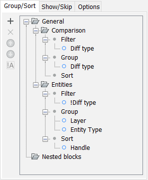
- In the Structure Tree expand the Entities node. All entities in the drawing are listed grouped first by the Layer property.
- In the Structure Tree select the node with the desired layer name. All entities belonging to this layer are automatically selected in the Model space.
- Press the Delete key. All layer's entities have been removed.
- Open the Structure panel (
- Delete all the lines in a drawing (mechanical CST file)
-
- Open the Structure panel ().
- Click the drop-down menu button () and select the mechanical configuration.Note: To inspect the selected configuration click the Configure structure tree option in the drop-down menu.
- In the Structure Tree expand the Entities node. All entities in the drawing are listed grouped first by the Entity property.
- In the Structure Tree select the Lines node. All the lines in the drawing are automatically selected in the Model space.
- Press the Delete key. All the lines in the drawing have been removed.
- Open the Structure panel (
How to work with rules
The principle of the Structure panel is comparing values of entity properties. The rules for the comparison process are stored in Structure Tree Configuration files (CST). The entities are then grouped in a structure tree based on the comparison's results. Grouping entities in the structure tree allows you to easily select entities with the same property value, check whether everything is as expected, or make changes to their properties.
You can decide how the entities are displayed in the structure tree by selecting a Structure Tree Configuration or creating a new one via the Configure Structure Tree dialog box. This dialog box lets you add rules defined by filters with results organized by grouping and sorting criteria. You can choose any entity type property BricsCAD recognizes (CAD, BIM, Mechanical, etc.) and custom properties as filtering, grouping, or sorting criteria.
 ) and Move property down (
 ) buttons in the Configure Structure Tree dialog box to change the position of the selected rule/property as needed.
- Rules
-
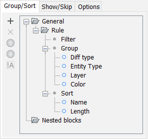
Each rule is marked by a folder in the Configure Structure Tree dialog box.
All entities in the drawing try to fit under existing rules in top-down order by checking each rule's filters. Entities that do not fall under a specific rule's filters pass to the following rule in the structure to be analyzed by its filters.
When at least one entity falls under a rule, the Structure panel shows a corresponding node in the Structure Tree containing the rule's filtered entities. The Structure Tree displays these entities in the node in the order dictated by the rule's grouping and sorting criteria.
- Filter
- Filters control whether an entity will be listed under a certain rule. If the filter does not apply to the entity the entity is passed on to the next rule in the tree.Note: Filtering is done by checking whether an entity has a certain property, not a property value. For example, if you filter on dimension style (select Dim style property as a filter), all entities with a dimension style will be included, meaning all dimensions. You cannot filter on Dim style is equal to ISO-25.Filters are additive. To have new entities listed under the same rule, select the rule's Filter node, click the Add rule or property button (
 ) and select a different entity property (for example, if you have a Dim style property filter and add a Radius property filter, all dimensions, as well as circles and arcs, will be listed under that rule).Note: In this case, the order in which you add the new criteria in the Configure Structure Tree dialog box does not matter.
Click the Toggle negation button on a selected filter to exclude the entities from being listed under the rule. The "!" sign appears in front of the filter's name.
If a rule has no filters, all entities other rules above it have not yet filtered fall under this rule. This is a catchall method for grouping and sorting the remaining unfiltered entities. Rules placed directly under a no-filter rule have no entities, as none is left to filter.
- Group
- A group defines how the entities filtered within a rule are displayed in the Structure Tree. The sequence of the items in the group deals with the nesting of Structure Tree's branches.
- To add a property to a Group node, select the desired node, then click the Add rule or property button ().
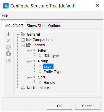
- Two commonly used properties for grouping are Layer and Entity Type. To display entities in the Structure Tree:
- grouped by layer and sub-grouped by entity type, move the Layer property above the Entity Type property in the configuration tree.
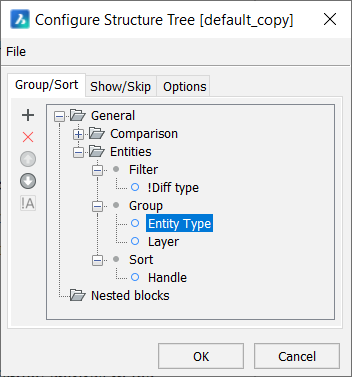
- grouped by entity type and sub-grouped by layer, move the Entity Type property above the Layer property in the configuration tree.
- grouped by layer and sub-grouped by entity type, move the Layer property above the Entity Type property in the configuration tree.
- To delete a grouping property, select it and click the Delete rule or property button (
 ).
).
- Sort
- Sorting defines how entities are listed in the deepest branch.
When applying sorting, the entities within a group are labeled with the value of their sorting property and displayed in a flat list (no sub-nodes).
If more properties are added as sorting criteria, the first listed property that applies to a node's entities is the one used for labeling.
- Predefined rules
- There are two predefined rules in the Structure panel's [default] CST configuration, Comparison and Entities.
Procedure: filter all dimension entities in a drawing
To have all dimensions in a drawing displayed under one node in the Structure Tree, do the following:
- Right-click the name of your drawing in the Structure panel, then choose Configure in the context menu to open the Configure Structure Tree dialog box.
- Go to File and choose Save as... option. Give a name to the new configuration file (for example, 'dim_filter') and save it. The default folder for CST files is the Support folder: C:\Users\%username%\AppData\Roaming\Bricsys\BricsCAD\V26x64\en_US\Support
- Go to Group/Sort tab and click the Add rule or property button. A new Rule is added at the end of the structure.
- Click the new rule's name and rename it 'Dimensions'.Note: Renaming the new rule with a distinct name is essential to have an actual filtering effect in the panel's Structure Tree.
- Click Dimensions rule's Filter node and click the Add rule or property button to display the Select property dialog box.
- In the Select property dialog box's search field type 'dym style'. Use the Find next button (
 ) or press Enter to jump to the Angular dimension Dym style property.
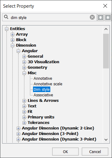
- Click OK to add the Dym style dimension property to the rule.
- In the Configure Structure Tree dialog box select the Dimensions rule. Click the Move property up button until the Dimensions rule is placed above the Entities rule.
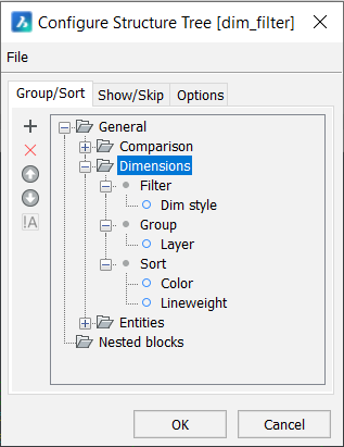
The Structure Tree's Dimensions node in the Structure panel now displays all the dimension entities in the drawing.