FIELD command
Inserts a field into the drawing, representing a selected property.

Icon: 
Method
The command opens the Field dialog box. Select a field name and a property to configure, and then click OK. You are prompted to specify the start point to insert the configured field into the drawing. If you want to modify the insertion settings, use the Command line options.
Options within the command
- Height
- Allows you to specify the height of the field text.
- Justify
- Allows you to choose a justification option to specify how the text is aligned relative to its insertion point.
Choose between Top Left, Top Center, Top Right, Middle Left, Middle Center, Middle Right, Bottom Left, Bottom Center, or Bottom Right.
The Field dialog box allows you to insert a field in a single or multiline text, table cells, attributes, and so on.
Click the arrow next to a category in Field names to expand it, then select a field name to see its properties.
Date & Time
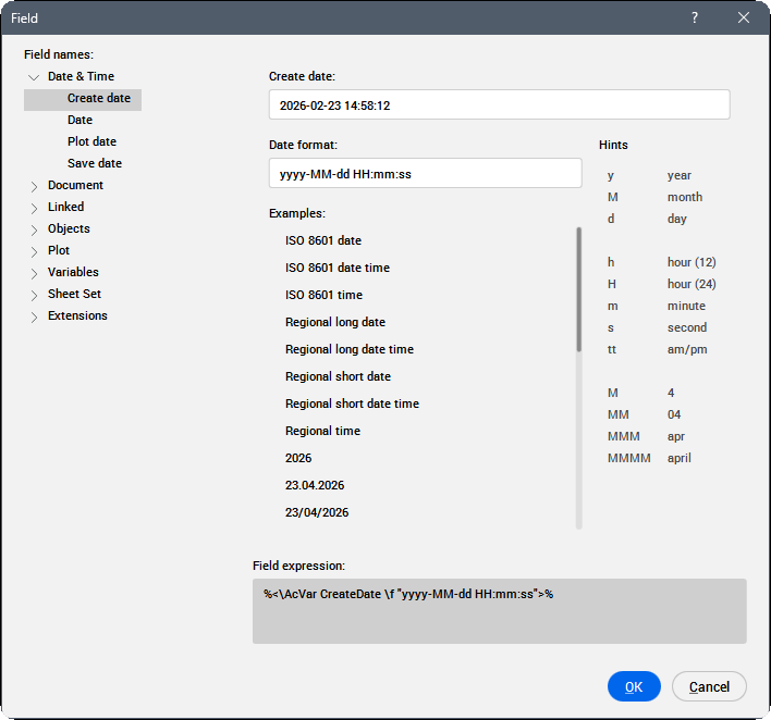
- Create Date
- Displays the last revision date of the drawing.
- Date
- Displays the current date.
- Plot Date
- Displays the date when the drawing was last plotted.
- Save Date
- Displays the date when the drawing was last saved.
- Date format
- Select a date format from the list or type a format in this field.
- Examples
- Displays date format examples.
- Hints
- Explains the meaning of the digits used in the date format acronym/abbreviation definition.
- Field expression
- Displays the field expression of the selected date. An operand in an expression can be a DisplayPropertyName surrounded with arrow brackets (<>).
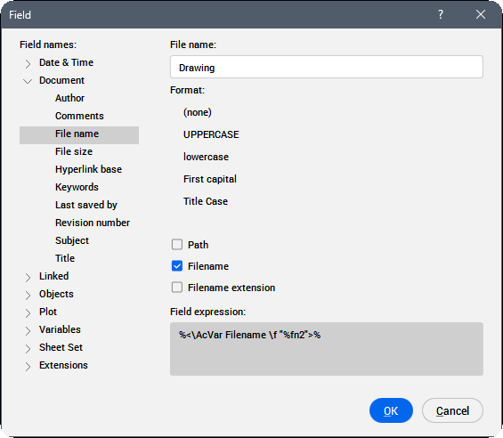
Document
- Author
- Displays the author of the document.
- Comments
- Displays the comments in the document.
- File name
- Shows the file name. It can include the path and the extension of the file.
- File size
- Displays the file size expressed in Bytes, Kilobytes and Megabytes.
- HyperLink base
- Displays the default path for the relative hyperlink in drawings.
- Keywords
- Displays the keywords for the opened file.
- Last saved by
- Displays the name of the person that last saved the file.
- Revision number
- Displays the drawing revision number.
- Subject
- Displays the subject of the drawing.
- Title
- Displays the title of the drawing.
- Format
- Displays the format of the selected category.
- Field expression
- Displays the field expression of the selected date. An operand in an expression can be a DisplayPropertyName surrounded with arrow brackets (<>).
Linked
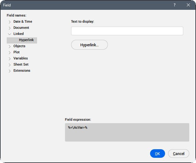
- Text to display
- Enter the text to be displayed for this hyperlink.
- Hyperlink
- Opens the Edit Hyperlink dialog box.
Objects
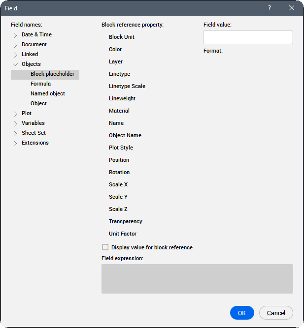
- Block placeholder
-
See the ATTDEF command to create block property fields in an attribute. When such an attribute is included in a block definition, the field displays the current value of the block property.
- Block reference property
- Displays the block reference property.
- Block name
- Displays the name of the property.
- Format
- Specifies the format for displaying the property.
- Formula
- Creates a formula field. You can use the values of table cells in a formula field. Click the Average, Sum, Count or Cell button. The Field dialog box closes to allow you to select cells in a table in the drawing. Also, you can enter the formula manually, for example, if you know the table handle.
- Named object
-
Creates a field that shows the current name of a named entity.
- Click the Named object type field, then select the object type in the list.
All named objects of the selected type are listed in the Name list box.
- Select a name in the list.
- Choose a format.
- Click the OK button to place the field.
- Click the Named object type field, then select the object type in the list.
- Object
-
Creates a field that shows a property of a selected entity.
- Click the select button, next to the Object type field.
The Field dialog box temporarily closes.
- Select an entity in the drawing.
The properties of the selected entity are listed in the Property list.
- Select a property in the list. Custom properties of all parameter types and visibility states for dynamic blocks and block references are also available.
- Choose a format.
- Click the OK button to place the field.Note: Attributes with fields are updated after REGEN and UPDATEFIELD commands.
- Click the select button, next to the Object type field.
Plot
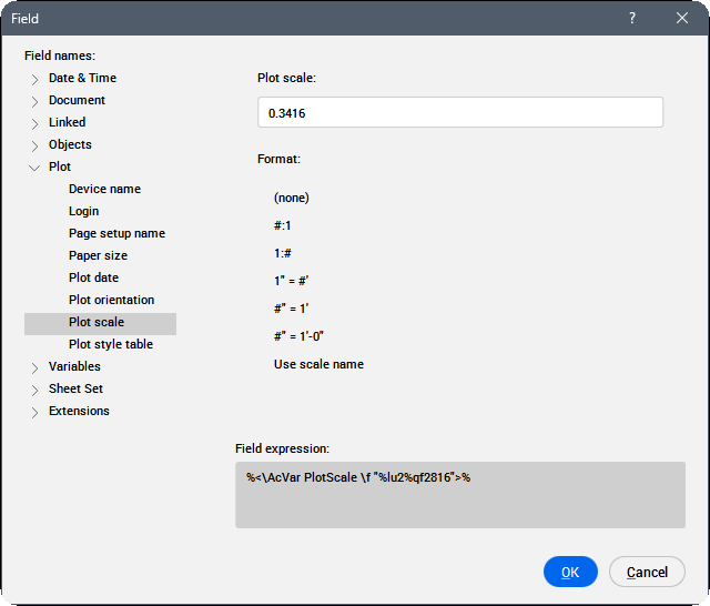
Plot fields apply to paper space layouts.
Allows you to create fields which show the current print settings of a layout.
Variables
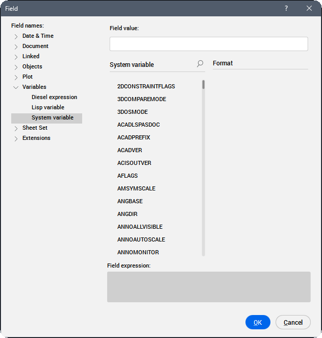
Allows you to create fields which show the current value of Diesel Expressions, Lisp Variables and System Variables.
It is possible to search for a specific variable in the Lisp Variables and System Variables lists using:
- Key navigation: press the up/down arrows to navigate in the list.
- Search bar: allows you to search for specific variables. The list is shortened to display only the variables that contain the entered sequence of characters.Note: To enable the search bar:
- Click the
 icon.
icon. - Press the Crtl+F key. The focus needs to be in the variable list. You can use the TAB key to cycle focus.
- Click the
Sheet Set
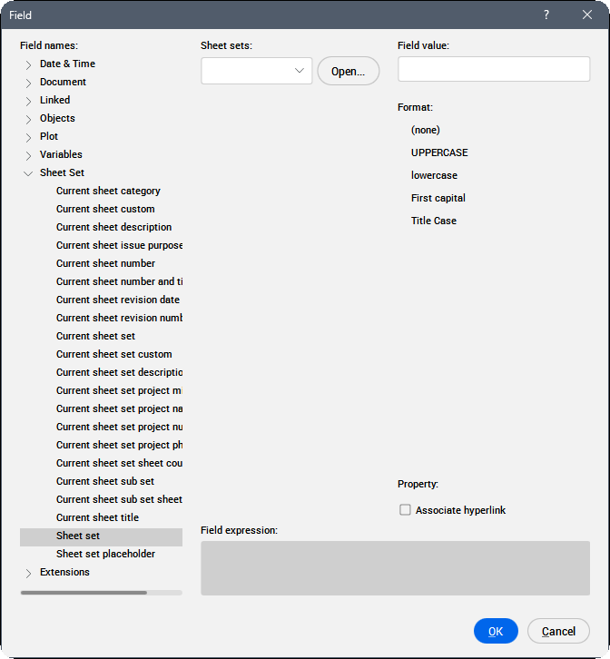
Allows you to create fields which show default and custom sheet set properties. With the Sheet Set property, a sheet navigation tree is opened.
Extensions
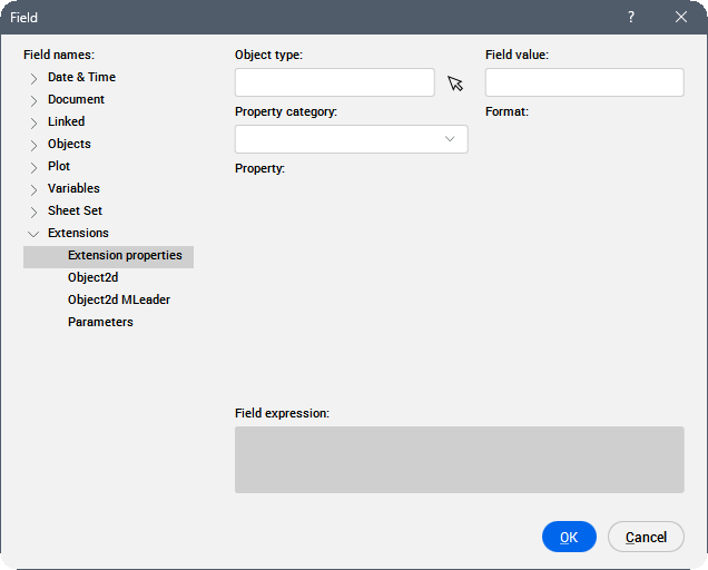
Allows you to create fields that show properties of entities specific to BricsCAD, such as BIM or Mechanical entities, displaying cached values in AutoCAD®.
- Extension properties
- Allows you to create fields with properties of a selected BIM or Mechanical entities.
- Object2d
- Allows you to create fields with properties of 3D entities by selecting the associated 2d entity inside BIM section block.
- Object2d MLeader
- Allows you to create fields inside MLeader with properties of 3D entities by selecting the associated 2d entity inside BIM section block using MLeader's arrow.
- Parameters
- Allows you to create fields referencing parameters in the drawing.Note:
- For block parameters, use the FIELD command inside a BEDIT session.
- After changing parameter values (from the Properties, Parameters Manager, or Mechanical Browser panel) use the REGEN, REGENALL, or UPDATEFIELD command to update the value displayed in the created field.
Field expression
Displays the expression of the field. You can learn how fields are structured by reading this code.