Mechanical Browser panel
- Run the MECHANICALBROWSEROPEN command.
- Right-click a ribbon panel or toolbar and choose Mechanical Browser from the Panels list.
The Mechanical Browser panel provides a central location for viewing and modifying the parametric properties of all mechanical blocks and non-mechanical blocks (solids).
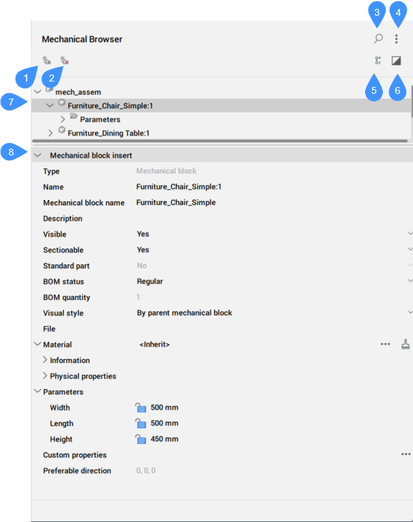
- Group by entity
- Group by type
- Show search
- Settings
- Sort Alphabetically
- Show selected
- Mechanical entities list
- Properties
Group by entity
Groups 3D constraints by entity. Expand an entity to view its associated constraints.
Group by type
Groups 3D constraints by type. Expand a constraint to view the affected entities.
Show search
Opens the search field
- Search field
- Searches the mechanical browser tree for the entered string. The search acts as a filter, so the browser displays all mechanical blocks whose names or sub-mechanical block names (or part of the names or block names) match the string. Click the X button on the right of the search field to close the field.
Settings
- Expressions of constraints
- Controls whether the numeric value or the assigned parameter name displays.
- Block parameters
- Controls the visibility of mechanical blocks parameters.
- Expressions of block parameters
- Controls the visual representation of mechanical blocks parameters: numeric value or assigned parameter name.
- Nested mechanical blocks of standard parts
- Controls the visibility of mechanical blocks of standard parts which are mechanical assemblies.
- Arrays of entities
- Toggles the display of Array nodes in the browser tree, including mechanical blocks arrays.
- Block and External references
- Toggles the display of Block References and External References nodes in the browser tree. Also, toggles node building in the Bodies folder for Block entities.
- Keep values list order
- Toggles the sorting of the values list for parameters inside the drop-down list.
- Asynchronous properties load
- Controls if the Mechanical Browser collects properties asynchronously if more than one node is selected in the Mechanical Browser tree.
- Expose all solids
- Toggles the display of solids for mechanical blocks and solids not related to constraints under the Bodies folder.
Sort Alphabetically
Lists all mechanical blocks, 3D constraints and solids alphabetically. Otherwise, they are listed in the order they are added to the assembly.
Show selected
When is activated, only nodes corresponding to selected objects or their parents are displayed.
When is activated and no objects are selected, or selection is cleared, the full model is shown in the browser.
The state of the Show selected mode is remembered between sessions, and is the same for all opened documents.
Mechanical entities list
Displays a hierarchical tree list of the assembly entities, such as user parameters, dimensional constraint parameters, dimensional constraints, mechanical blocks, arrays and solids. Top-level nodes can have sub-nodes. For example, constraint node have sub-node(s) for its argument(s). An array node has sub-nodes for its arguments, etc.
Click the arrow to the left of a node to expand or collapse it. Click the node to select the mechanical block in the Model Space. Press the Ctrl or Shift key to select multiple nodes.
Right-click a node to open the associated context menu, that differs depending on the selected node. You can also select a group of nodes and open a context menu for them. The context menu contains only elements applicable to each selected node.
- Context menu of the root mechanical block assembly
-
- Remove material from mechanical block
- Allows you to remove the assigned material for the mechanical blocks.
- Update
- Updates the mechanical block assembly hierarchy for the current drawing when the reference drawing files of the mechanical block subassemblies have been modified.
- Visual style > All by Viewport
- Applies the current visual style to all mechanical blocks in the assembly.
- Switch all to local
- Converts all external mechanical blocks in the model to local mechanical blocks.
- Switch all to external…
- Switches all internal mechanical blocks to external mechanical blocks.
- Add new parameter
- Creates a new parameter in the assembly.
- Custom properties
- Opens the Mechanical Properties dialog box to define custom properties for the drawing.
- Select all
- Selects all mechanical blocks with the same definition.
- Select same
- Selects all mechanical blocks with the same name and the same parameter values.
- Highlight all
- Highlights all mechanical blocks with the same definition.
- Highlight same
- Highlight all mechanical blocks with the same name and the same parameter values.
- Create sequence
- Creates a block with a representation of the current assembly.
- Renumerate child nodes
- Renumerates all child nodes according to their types.
- Renumerate child nodes continuously
- Renumerates all child nodes with continuous numeration when applicable.
- Collapse all
- Collapses all top-level nodes and their sub-nodes.
- Expand all
- Expands all top-level nodes and their sub-nodes.
- Context menu of child (non-root) mechanical blocks, internal or external
-
- Open
- Opens the referenced drawing (see the BMOPEN command).
- Open a copy
- Opens a copy of a mechanical block insert as a new drawing (see the BMOPENCOPY command).
- Update
- Reloads all referenced mechanical blocks from external files and updates BOM tables (see the BMUPDATE command).
- Replace…
- Replaces a mechanical block insert (see the BMREPLACE command).Note: Replacing a local insert turns it into an external insert.
- Replace all inserts...
- Replaces all inserts that refer to the same source (see the BMREPLACE command).
- Switch to local
- Switches an external mechanical block to an internal mechanical block (see the BMLOCALIZE command).
- Switch to external
- Switches an internal mechanical block to an external mechanical block (see the BMEXTERNALIZE command).
- Set material to mechanical block...
- Opens the Physical Materials dialog box, which allows you to assign a physical material to the mechanical block.
- Remove material from mechanical block
- Removes the physical material definition for a local mechanical block.
- Mechanical block's BOM status
- Controls the appearance of the mechanical block in BOM tables.
- Dissolve
- Removes the selected feature from the assembly, but keeps its geometry. However, the design intent (spatial and parametric relationships between the feature’s faces) associated with the geometry of a dissolved feature is removed.
- Custom properties
- Opens the Mechanical Properties dialog box to define custom properties for the drawing.
- Reset instance custom properties
- Resets instance custom properties to defaults inherited from a corresponding block.
- Hide / Show
- Hides / Shows the mechanical block.
- Make mechanical block standard / Make mechanical block non-standard
- Changes the type of the mechanical block.
- Include all inserts to section...
- Sets the Sectionable property of all similar inserts to YES. Defines whether an insert is affected by the VIEWSECTION command.
- Exclude all inserts to section
- Sets the Sectionable property of all similar inserts to NO. Defines whether an insert is affected by the VIEWSECTION command.
- Visual Style
- Sets a visual style for the mechanical block.
- Zoom to
- Zooms to the selection set.
- Select all
- Selects all mechanical blocks with the same definition.
- Select same
- Selects all mechanical blocks with the same definition and the same parameter values.
- Highlight all
- Highlights all mechanical blocks with the same definition.
- Highlight same
- Highlights all mechanical blocks with the same definition and the same parameter values.
- Delete
- Deletes the mechanical block, similar with the SMDELETE command. In this case, the feature is removed from the browser and the geometry is changed depending on the type of the feature.
- Renumerate similar nodes
- Renumerates all nodes of the same type and the same level.
- Context menu of parameters
-
- Geometry-driven
- If ticked, it makes the parameter geometry-driven.
Note: If the parameter is assigned to a geometry-driven 3D constraint, its boundaries are taken into account while moving the constrained geometry.- Create design table
- Creates a design table to drive parametric block parameters.
- Animate
- Animates models by means of parameters.
- Convert
- Converts a 2D dimensional constraint to a dimensional constraint parameter, or a user parameter to a user variable and vice versa.
- Context menu of sub-assembly mechanical block parameters
-
- Link to parameter
- Links sub-assembly mechanical block parameter to the main mechanical block level parameter.
- Context menu of Constraints
-
- Enabled
- Toggles the enabling of the constraint.
- Flip side
- Flips the side of the constraint (not available for fix constraints).
- Select geometry
- Selects the entities involved in the constraint.
Note: For more options, see the DMCONSTRAINT3D command.
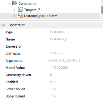
- Context menu of dimensional Constraints
-
- Geometry-driven
- If ticked, it makes the constraint geometry-driven.
Note:- If the parameter is assigned to a geometry-driven 3D constraint, its boundaries are taken into account while moving the constrained geometry.
- You can set upper and lower bounds in the Mechanical Browser panel, which are taken into account in dynamic operations, like DMMOVE and ROTATE3D.
- Create design table
- Creates a design table to drive parametric block parameters (see the Parameters Manager panel).
- Context menu of constraint arguments
-
- Flip
- Reverses direction.
- Replace...
- Replaces the current argument with a another one (see the DMCONSTRAINT3D command).
- Exclude
- Excludes the current argument.
Properties
Displays the properties of the selected entity. If several nodes are selected in the tree, the Properties section displays the properties available of all the selected nodes. Changing a property modifies all the selected nodes.
Change a property by clicking a numeric field to edit its value or by selecting another option from the drop-down list, which is opened when you click the down arrow from the right side of the field.
The most important properties of a mechanical block are:
- Extension type: defines the extension type for the mechanical block.
- Sectionable: defines if the mechanical block is sectionable.
- Standard part: defines if the mechanical block is a standard part.
- BOM status: defines the BOM status.
- Material: defines the material.
- Custom properties: displays the custom properties.Note: Click the browse button (
 ) to open the Mechanical Properties dialog box.
 - Preferable direction: indicates the direction for exploded views, which is set with the BMEXPLODECONFIG command.