FITARC command
Fits an arc or a circle to entities.

Description
Draws an arc or circle fitted to one or more entities. The command minimizes accumulated perpendicular distances to the points of the selected entity(ies).
Methods
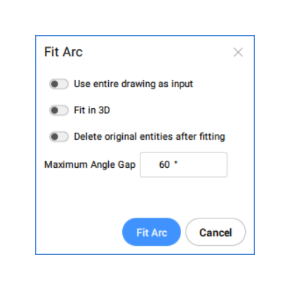
This command opens the Fit Arc command panel.

The options within the FITARC command are the same as the options in the Fit Arc command panel.
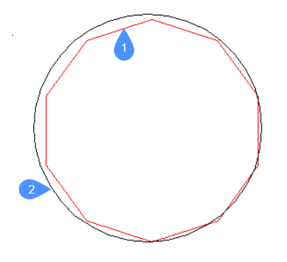
The entities and the results of this command are shown in the examples below:

- Points used by the command to fit the arc.
- Arc fitted to the points.

- Polyline used by the command to fit the arc.
- Arc fitted to the polyline.
Options within the command
- use Entire drawing
- Use all entities in the drawing as input.
- Fit in 3d
-
This option applies when one or more input entities do not lie in the XY-plane.
If checked, the resulting arc or circle is created in 3D space, otherwise the input entities are projected onto the XY-plane first.
Note: The XY plane used for projection is the one of the current UCS (User Coordinate System). This allows the user to make the fit in any plane.
- Delete original entities after fitting
- When this option is set to Yes, the initial entities are deleted.
- maximum Gap angle
- Defines the threshold value for the maximum angle gap between the characteristic points of the input entities. If the maximum gap angle is larger than the threshold value, an arc is created. Otherwise, a circle is created.
- selection options (?)
-
Allows to choose a selection method. See the SELECT command.
Note: The options Use entire drawing, Fit in 3d, and Delete original entities after fitting can be set using the system variable FITLINEFITARCMODE. The option Maximum gap angle can be set using the FITARCMAXGAP system variable.

