HATCH command
Opens the Hatch and gradient dialog box.

Icon: 
Alias: BH, H
Description
Opens the Hatch and gradient dialog box to create a hatch entity in the current drawing.
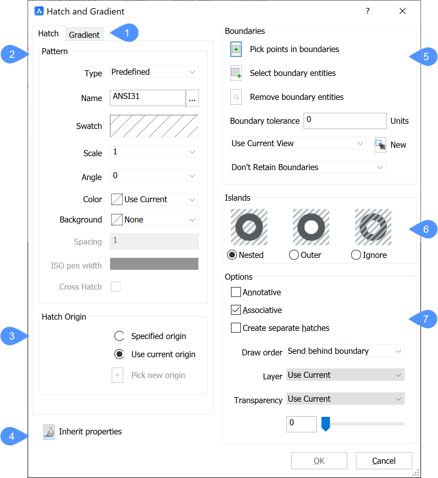
The Hatch and Gradient dialog box allows you to fill closed 2D areas with repeating patterns or solid colors.


- Hatch and Gradient tabs
- Hatch Pattern
- Hatch origin
- Inherit properties
- Boundaries
- Islands
- Options
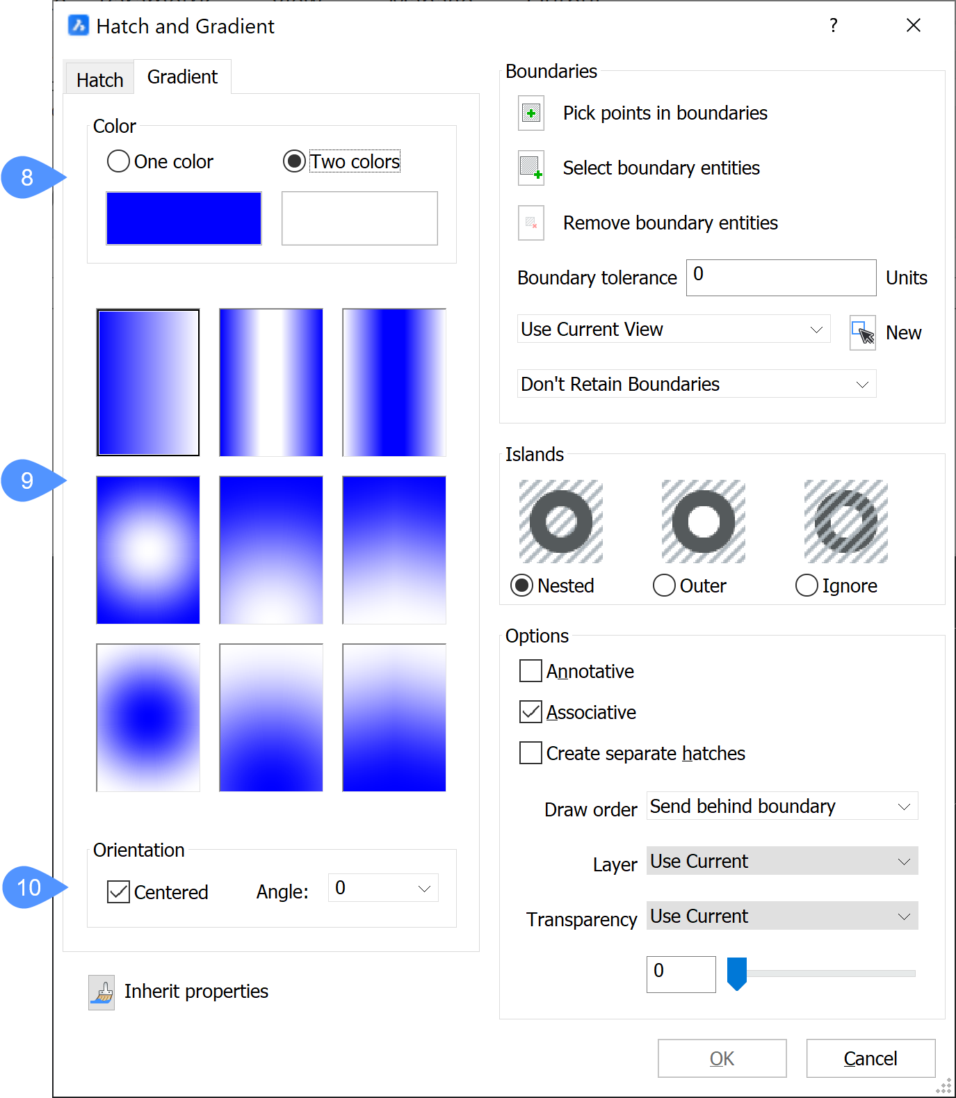
- Gradient Color
- Gradient pattern
- Gradient Orientation
Pattern
Specifies the hatch pattern properties.
- Type
- Specifies the type of hatch.
- User defined
- Constructs the pattern from the user-defined parameters of Angle, Spacing, Color, Background and Cross Hatch.
- Predefined
- Uses the patterns defined in the iso.pat (metric units) or default.pat (imperial units) pattern definition files provided with the program.
- Custom
- Uses a pattern defined by *.pat files (limited to one pattern definition per file) created by users. The program searches for *.pat files in the folders that are defined in the SRCHPATH system variable.
- Name
-
Specifies the name of the predefined hatch pattern by one of these methods. Click the Browse button to display the Hatch Pattern Palette dialog box, to choose a pattern.
Note: This option is unavailable for the User-defined patterns.
- Swatch
-
Displays the Hatch Pattern Palette dialog box.
Note: This option is unavailable for the User-defined patterns.
- Scale
-
Sets the scale factor of the pattern. To use an enlarged hatch pattern, enter a value bigger than 1.
Note: The scale factor of hatch patterns is generally the same as that for text and linetypes.
- Angle
-
Sets the angle of the pattern.
Note: This angle is measured relative to the positive x-axis of the current UCS.
- Color
-
Sets the color of the hatch pattern lines.
Note: For the Use Current option, the current color specified by the CECOLOR system variable is used.
- Background
- Sets the color of the background of the hatch.
- Spacing
-
Specifies the distance between hatch lines.
Note: This option is available for only user defined patterns.
- ISO pen width
-
Specifies the lineweight.
Note: This option is available only for ISO hatch patterns.
- Cross Hatch
-
Determines whether the pattern is crossed (repeated at 90 degrees to the original).
Note: This option is available only for user defined patterns.
Hatch origin
Specifies the origin of the hatch. Either the current or a new specified origin can be chosen.
Inherit properties
Copies the properties of another existing hatch pattern to use with this pattern.
Boundaries
Specifies the boundary conditions of the hatch.
- Pick points in boundaries
-
Specifies the closed areas (boundaries) in which to place the pattern.
Note: You cannot pick an area that already contains a hatch pattern, or areas that are not closed (whose gap is larger than the value specified by Boundary tolerance).
- Select boundary entities
-
Selects the entities that make up the hatching boundary to constrain the extent of the pattern.
Note: This option allows you to hatch closed areas, including ones that already contain a hatch. It hatches open areas whose gap is less than the value specified by Boundary tolerance.
- Remove boundary entities
- Remove entities from the detected boundary set.
- Boundary tolerance
-
Specifies the largest gap the program ignores when hatching a boundary that is not fully closed.
- 0 - (Default): the tolerance is set by the application, based on the current view size. When zoomed in closely, boundary detection will fail; when zooming out further so the contour 'looks' closed, the boundary will become detected
- Any Value : defines the maximum gap in drawing units.
Note: The value is saved in the HPGAPTOL system variable.
- Use current view / boundary set
- Specifies where the program should search for entities that make up the boundary.
- New
-
Creates a new selection set of entities that make up the pattern boundary.
Note: The next step is to click the Pick Points in boundaries button to choose the hatch area.
- Retain boundaries
- Determines what happens to boundaries.
- Don't Retain Boundaries
- Removes the boundary after the hatch is created.
- Retain Boundaries as Polylines
- Retains boundaries and turns them into polylines.
- Retain Boundaries as Regions
- Retains boundaries and turns them into regions (Pro or Superior versions only).
Islands
Specifies how BricsCAD® will respond when other boundaries are present within the closed hatch boundary.
- Nested
-
When a closed hatch boundary contains other boundaries, BricsCAD® hatches alternating areas.
- Outer
-
When a closed hatch boundary contains other boundaries, BricsCAD® hatches only the outermost area.
- Ignore
-
When a closed hatch boundary contains other boundaries, BricsCAD® hatches all interior areas, as if they were not present.
Options
- Annotative
-
Toggles the Annotative property of the hatch. When turned On, BricsCAD® applies the current annotative scale.
Note: When this option is turned on, the Associative option is unavailable.
- Associative
-
Toggles the associativity of hatch patterns: when the boundary is changed, the pattern automatically updates itself.
Note: This option is not available for annotative hatches.
- Create separate hatches
-
Toggles how multiple hatches are treated. If turned On, BricsCAD® creates a separate hatch entity for each boundary in the selection set.
- Draw order
-
Specifies where the pattern should be placed relative to overlapping entities.
- Layer
-
Specifies the layer on which the hatch should be placed.
- Transparency
-
Set the transparency property of the hatch.
Note: For the Use current option, the transparency value, defined by the CETRANSPARENCY system variable, is applied.
Gradient Color
Specifies the gradient color. The gradient can include either one color or two colors to create a solid fill hatch.
Gradient pattern
Specifies the pattern of the gradient.
Gradient Orientation
Specifies how the fill is placed in the boundary.
- Centered: centers gradient fill in the area to be filled; when off, starts the fill from the upper left of the boundary.
- Angle: select an angle of the gradient fill, relative to the current UCS; choose from increments on 15 degrees, or else enter any other value for the angle.

