RENDERPRESETS command
Creates and edits properties for renderings through Drawing Explorer dialog box.

Icon: 
Alias: ROPTIONS
Description
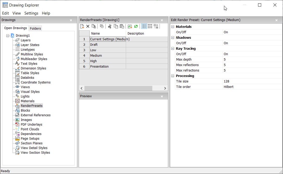
Opens the Drawing Explorer dialog box with RenderPresets category selected to view and modify render presets in the current drawing.

Options within the Edit Render Preset panel
- Materials
-
Toggles the use of materials in a rendering.
Note: Materials are applied to layers and entities. See MATERIALS command.- On
- Uses material definitions for rendering.
- Off
- Does not use materials.
- Shadows
-
Toggles the use of shadows in the rendering.
- On
- Uses shadows for rendering.
- Off
- Does not use shadows.
- Ray Tracing
-
Tracks each ray of light from each light source as it travels through the scene and bounces off entities.
- On
- Uses ray tracing.
- Off
- Does not use ray tracing.
- Max Depth
- Specifies the maximum total number of times light bounces and refracts.
- Max Reflections
- Specifies the maximum times that light beams bounce off entities.
- Max Refractions
- Specifies the maximum times that light refract through transparent entities.
- Processing
- Specifies how the rendered image is processed, applied to renderings sent to a separate window.
Context Menu Options
- New
- Creates additional Render Preset definitions into the drawing. Displays the New Render Preset dialog box.
- Delete
-
Deletes Render Preset definitions from the drawing. The following Render Preset definitions cannot be deleted:
- Draft
- Low
- Medium
- High
- Presentation
- Set current
-
Sets the selected Render Preset as current.
Note: The current render preset is used by the RENDER command or when printing using the shade plot type Rendered as defined in Shade plot setting in the PAGESETUP and the PRINT commands. The name of the current render preset displays between brackets: e.g. Current Settings (Medium).Note: You can override the properties of a preset in the Edit Render Preset pane. When overrides exist, an asterisk displays in front of the current render preset name: e.g. Current Settings (*Medium).
- Rename
-
Renames the Render Preset.
Note: Following Render Preset items cannot be renamed:- Draft
- Low
- Medium
- High
- Presentation
- Select All
- Selects all Render Preset definitions.
- Invert selection
- Deselects the current selection and vice versa.

