SMFLANGEEDGE command
Creates flanges to a sheet metal part.

Icon: 
Description
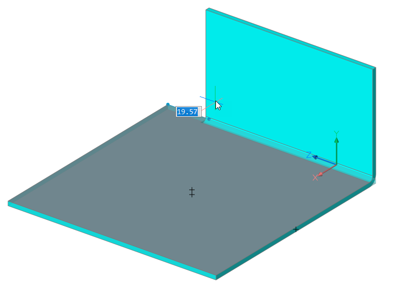
Creates one or more flanges to a sheet metal part by pulling one or more edges of an existing flange or lofted bend.
Options within the command
- Material Outside
- Creates a flange shifted by one material thickness to the outside.
- material Inside
- Creates a flange preserving the external dimensions of the parent flange.
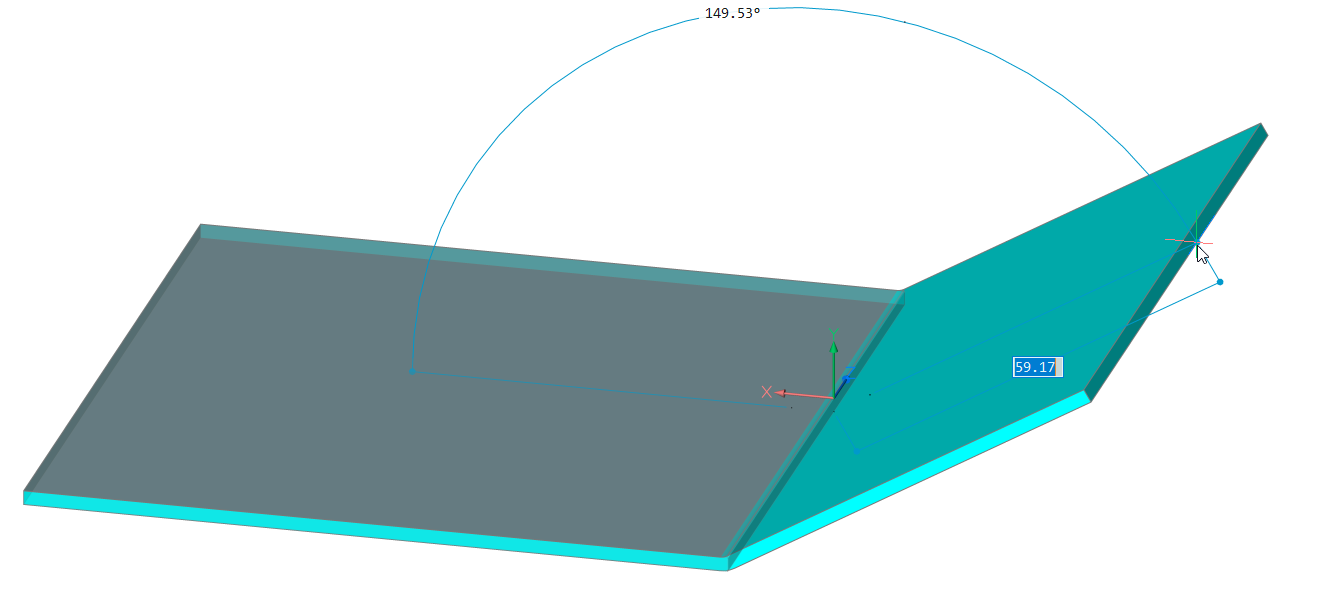
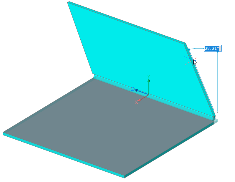
- Angle
- Allows you to first define the angle of the flange, then the length.
- Length
- Allows you to first define the length of the flange, then the angle.
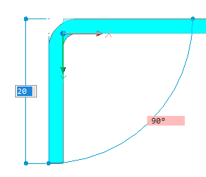
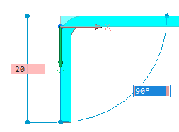
- Radius
- Defines the radius of the bend connected to the new flange.
- Taper angle
- Creates a flange with one or two tapered side faces.
- Back
- Goes back to the previous prompt.
- Skip
- Keeps the flange side orthogonal instead of tapering it.
- Width
- Allows you to define a different width than the length of the selected edge. By default, the flange width equals the length of the selected edge.
- Back
- Undoes the current width procedure.
- Skip
- Keeps the side edge of the flange at the end point of the edge.
Note: Taper angle and Width options are not available if multiple edges are selected.
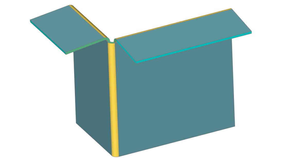
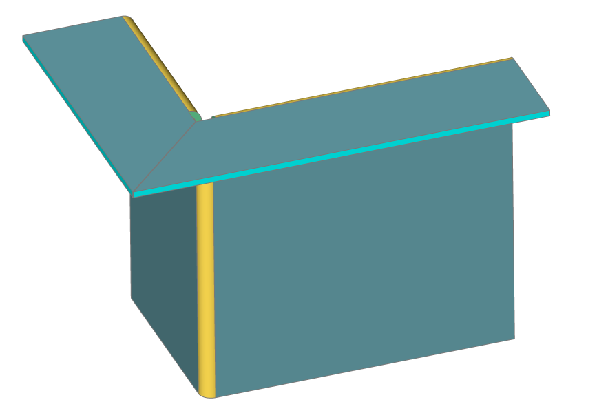
- Toggle connection
- Toggles between connecting or not connecting adjacent flanges when creating two or more flanges simultaneously.
-
-
Not connected
-
Connected
-
- set Direction
- Defines the angle of the flange by specifying a direction to be parallel to.
- 2Points
- Defines the direction by specifying two points.
- Entity
- Defines the direction by selecting an axial entity (for example, linear edges or planar faces).
- Last
- Uses the last used direction.
- View
- Uses the Z direction of the view.
- Xaxis
- Uses the X axis as direction.
- Yaxis
- Uses the Y axis as direction.
- Zaxis
- Uses the Z axis direction, if suitable.