SPLINE command
Creates a spline.

Icon: 
Alias: SPL
Description
Creates 2D and 3D nonuniform rational B-splines (NURBS) to produce precise, freeform shapes.
Method
Important: Splines can be created using either the fit points method or the control vertices method. When you run the command, the current method settings are displayed in the Command line. To change the settings, choose the Method option before specifying the first point.
Based on the current method settings, you are prompted to specify the first point, then the second point. Continue with the next points until you press Enter to end the command.
- Specify first point
- Specify the starting point for creating a spline.
- Specify second point
- Specify the second point of the spline.
- Specify next point
- Specify the next point of the spline.
Example:
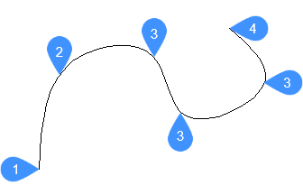
- First point of spline (no tangency)
- Second point
- Next point
- End point
Options within the command
- Entity
- Allows you to select entities to convert to splines.
- Method
- Allows you to select whether to use control vertices or fit points to generate the spline.Note: The SPLMETHOD system variable stores the last used method and sets it as the default. When BricsCAD starts, the system variable defaults to 0 (fit points).
- Fit
- Generates a degree 3 (cubic) B spline that passes through specified fit points.Note: If the tolerance value exceeds zero, the spline is required to remain within the specified tolerance distance of each point.
- Knots
- Defines the method used to blend component curves between successive fit points in a spline (knot parameterization).Note: The SPLKNOTS system variable stores the last used knot parameterization method and sets it as the default. When BricsCAD starts, the system variable defaults to 0 (chord).
- Chord
- Spaces the knots between component curves in proportion to the distances between each pair of corresponding fit points.
- Square root
- Spaces the knots between component curves so that each is proportional to the square root of the distance between its corresponding pair of fit points.
- Uniform
- Spaces the knots of each component curve, independent of the spacing of the matching points, so that they are equal.
- start Tangency
- Allows you to specify a tangency for the starting point.
- end Tangency
- Allows you to specify a tangency for the ending point.
- toLerance
- Sets the fit tolerance. Specify (in drawing units) how closely the spline matches its fit points. If the fit tolerance is 0, the spline passes through its fit points.
- CV
- Allows you to define control vertices to create a spline. This method generates splines of degree 1 (linear), degree 2 (quadratic), degree 3 (cubic), and up to degree 10.Note: The control vertices establish the control frame. To display or hide the control vertices and control frame, select or deselect the spline, or use the CVSHOW and CVHIDE commands.
- Degree
- Sets the polynomial degree of the resulting spline.
Note: The SPLDEGREE system variable stores the last used polynomial degree and sets it as the default. When BricsCAD starts, the system variable defaults to 3.
- Undo
- Removes the last point and continues drawing from the previous point.
- Close
- Automatically draws a spline segment between the start and end points to create a closed spline.