Allows you to edit a TIN surface.
Description
Allows you to edit existing TIN Surfaces. Editing options affect the way TIN edges connect TIN points to form triangles. You can also delete existing TIN points and edges or add new ones or change the position and elevation of existing TIN points.
Any TIN Surface editing operation can be modified in the Civil Explorer panel after the execution. It is also possible to change the chronological order of editing operations.
Options within the command
- Add Points
- Adds new points to the existing TIN Surface.
Note: These entities are added to the TIN Surface as drawing objects definitions.
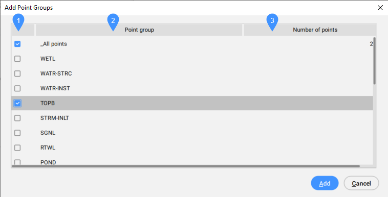
- A dialog box opens:
-
- Select box
- Point group
- Number of points
- Select box
- Allows you to select or deselect a point group to be included.
- Point group
- Lists all available point groups.
-
- Number of points
- Displays the number of points of the point group.
- Add Point Groups
- Adds Civil points from a specified Point Groups to the existing TIN Surface.
Note: By default, Civil points are placed in the “_All points” Point Group. Use the CIVILPOINTGROUP command to create a new Point Group.
- Add Breaklines
- Adds selected linear CAD objects to the TIN Surface as breaklines.
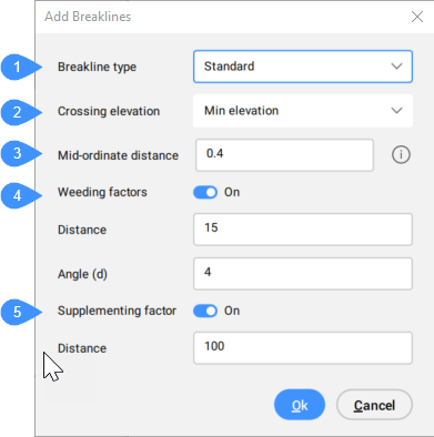
- A dialog box opens:
-
- Breakline type
- Crossing elevation
- Mid-ordinate distance
- Weeding factor
- Supplementing factor
-
- Breakline type (1)
- Displays the selected breakline type. Select the appropriate breakline type from the drop-down list.
- Standard
- Adds breaklines to the TIN Surface, re-builds the TIN Surface so that triangles follow the breaklines edges and elevations.
- Projected
- Projects breaklines to the TIN Surface and creates new triangles, without modifying TIN Surface elevations.
- Crossing elevation (2)
- Determines which elevation is taken for triangulation at the intersection of two breaklines, added in the same Add breakline definition.
-
- Not allowed
- The intersection is treated as one breakline.
-
- Min elevation
- The elevation of lower breakline is taken.
-
- Mid elevation
- The middle elevation between the crossing breaklines is taken.
-
- Max elevation
- The elevation of upper breakline is taken.
- Mid-ordinate distance (3)
- Adds supplementary TIN points along the arc according to the mid-ordinate distance which is used for arc approximation.
- Weeding factor (4)
- Toggles the using of weeding factor.
-
- Distance
- Sets the weeding distance.
-
- Angle (d)
- Sets the weeding angle.
Note: Existing breakline vertices are not used to create a TIN Surface, if the distance and angle between them is less than the specified weeding parameters.
- Supplementing factor (5)
- Toggles the using of supplementing factor.
-
- Distance
- Sets the supplementing distance.
Note: Additional vertices are added to breakline, if the distance between vertices on the breakline is greater than the specified supplementing distance.
Note: The Supplementing and Weeding factor are disabled for the Projected breaklines.
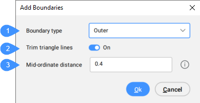
- Add bOundaries
- Adds selected linear CAD objects to the TIN Surface as boundaries.
- A dialog box opens:
-
- Boundary type
- Trim triangle lines
- Mid-ordinate distance
-
- Boundary type (1)
- You can choose the boundary type from the drop-down menu:
- Show
- Displays triangles inside the boundary polygon.
- Hide
- Hides triangles inside the boundary polygon.
- Outer
- Defines the outer boundary of the TIN Surface. All the triangles outside the boundary are hidden.
Note: Triangle lines are not trimmed by default.
- Clip
- Clips an existing TIN Surface in the drawing with a selected polygon as the clipping boundary for the surface.
- Does not change the TIN Surface boundary, but affects all elements (TIN operations) added to the TIN Surface after the Clip boundary. Only elements, located inside the Clip boundary affects triangulation.
-
- Trim triangle lines (2)
- Yes: trims the triangles (TIN edges) that intersect the boundary to follow the boundary polygon.
No: deletes all triangles that intersect the boundary polygon.
- Mid-ordinate distance (3)
- Adds supplementary TIN points along the arc according to the mid-ordinate distance which is used for arc approximation.
- Remove Points
- Removes points/vertices of triangles from the TIN Surface.
-
- Multiple
- Allows you to remove multiple TIN points at once.
- Swap Edge
- Swaps the selected TIN edges.
Note: Edges cannot be swapped in following cases:
- when the TIN edges lie on the breaklines.
- when the TIN edges are created with the Add line definition.
- when the TIN edge belongs to two adjacent triangles that form a concave envelope.
- Point Location
- Modifies the location of a single or multiple TIN points in one step.
-
- Multiple
- Requires a polygonal selection of multiple TIN points and specifying a base point for moving the TIN points.
- Point Elevation
- Modifies the elevation of a single or multiple TIN points in one step.
-
- Multiple
- Requires a polygonal selection of multiple TIN points. Then determine the new absolute elevation or delta elevation (elevation difference).
- Add Line
- Adds new TIN Edge between existing TIN points.
- Delete Line
- Deletes TIN Edges inside the specified selection area.
Note: The edges inside the selected area are colored red.
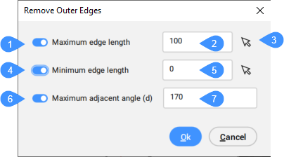
- Remove Outer Edges
- Removes triangles on the outer boundary of the TIN Surface, that have:
- greater edge length.
- shorter edge length.
- greater angle than specified.
You can specify which of these criteria is considered when removing the outer edges.
This method begins removing triangles from the outer boundary towards the inner part of the TIN Surface. It stops removing triangles, when the last outer triangle meets the specified criteria. That means that this method does not remove inside triangles.
A dialog box opens:
-
- Maximum edge length
- Maximum edge length value
- Pick points
- Minimum edge length
- Minimum edge length value
- Maximum adjacent angle (d)
- Maximum adjacent angle value (in degrees)
- Maximum edge length (1)
- Toggles the using of maximum edge length.
- Maximum edge length value (2)
- Sets the value for maximum edge length.
Note: Triangles with an edge exceeding the specified maximum edge length are deleted from the TIN Surface.
- Pick points (3)
- Allows you to set the value for maximum or minimum edge length by picking points in the drawing area.
- Minimum edge length (4)
- Toggles the using of minimum edge length.
- Minimum edge length value (5)
- Sets the value for minimum edge length.
Note: Triangles with an edge exceeding the specified minimum edge length are deleted from the TIN Surface.
- Maximum adjacent angle (d) (6)
- Toggles the using of maximum adjacent angle.
- Maximum adjacent angle value (in degrees) (7)
- Sets the value for maximum adjacent angle.
Note: Triangles with an inner angle exceeding a specified max. angle are deleted from the TIN Surface.
- Minimize Flat Areas
- Finds flat triangles and then swaps the adjacent TIN edges of those triangles so that their slope is non-zero.
This method is most useful when the TIN Surface is created from Contours. It starts at the concave side of the contours and swaps the edge of the first triangle so that its slope becomes non-zero. The process continues until the method still ensure that there are no flat triangles by swapping their edges.
Note: Minimize flat areas method swipes only the TIN edges that do not lie on breaklines.
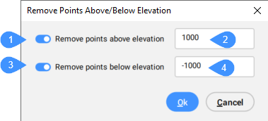
- Remove Elevations
- Removes TIN points below/above the specified elevation and displays the number of points removed.
A dialog box opens:
- Remove points above elevation
- Elevation greater than
- Remove points below elevation
- Elevation less than
- Remove points above elevation (1)
- Toggles the option to remove TIN points above a specified elevation.
- Elevation greater than (2)
- Sets the elevation above which TIN points are removed.
- Remove points below elevation (3)
- Toggles the option to remove TIN points below a specified elevation.
- Elevation less than (4)
- Sets the elevation below which TIN points are removed.


