Creates a broken view on drawing views generated by the VIEWBASE command in a paper
space layout.
Icon:
Note: This command operates only in Paper Space.
Note: This command can be entered transparently during
commands (‘viewbreak)
Method
Select the drawing view from which to generate the broken view by clicking inside the
drawing view. Select the first and the second points which specifies the first and
the second planes of the cuts.
The default direction of the symbol is based on the size of the viewport:
Vertical if the viewport is wider than high.
Horizontal if the viewport is higher than wide.
Options within the command
Type
Allows to set the broken symbol type:
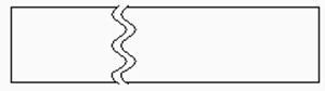
sTraight
Line geometry. Supports the Gap distance property.
Spline
Spline geometry. Supports the Gap distance, Width and
Height.
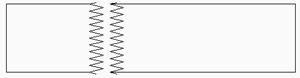
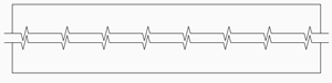
Zigzag
Spline geometry. Supports the Gap distance, Width and
Height properties.
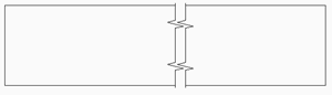
sMall zigzag
Supports the Gap distance, Width, Height and Step
properties.
Current
Use the last used broken symbol type.
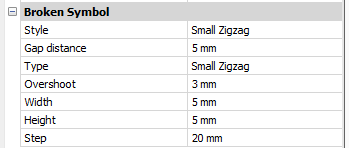
Note: The properties of the Broken Symbol can be
edited in the Properties panel:
Style/Type
Select the style / type in the drop-down list.
Gap distance
Defines the distance* between the two parts of the broken
symbol.
Overshoot
Defines the length of the extends for the break lines
outside of the 2D view.
Width
Defines the width* of the shape symbol in the symbol
direction.
Height
Defines the height* of the shape symbol in the direction
orthogonal to the symbol direction.
Step
Defines the distance* between the small zigzag symbols.
* Expressed in layout units.
Vertical
Aligns the symbol along the Y axis.
Horizontal
Aligns the symbol along the X axis.
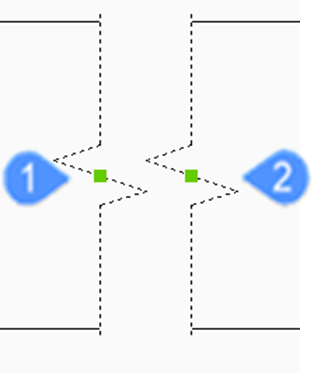
Edit Grips
You can edit break symbol grips.
Select the break symbol and 2 Grips display:
Controls the position of the first break plane in the model space
Controls the position of the second break plane in the model space