AMSURFSYM command
Creates a surface symbol.

Icon: ![]()
Method
Select the object to attach the surface symbol and specify the points for its location.
- Esistono due casi d'uso per attivare le entità meccaniche:
-
- Quando si crea un nuovo disegno che contiene entità meccaniche:
- Impostare la variabile di sistema LOADMECHANICAL2D su ON (1).
- Iniziare un nuovo disegno utilizzando un modello Mechanical2d.
- Quando si apre un disegno che contiene entità meccaniche:
- Impostare la variabile di sistema LOADMECHANICAL2D su ON (1).
- Aprire un disegno ACM esistente e avviate la creazione di simboli speciali.
- Quando si crea un nuovo disegno che contiene entità meccaniche:
Note: Queste quote sono compatibili con l'applicazione legacy AutoCAD® Mechanical.
Note: Le quote verranno aggiunte al layer AM_5.
Note: Dopo l'apertura di un disegno contenente entità meccaniche, il riempimento di altri disegni con dati correlati al meccanico verrà eseguito on-demand in contrasto con le versioni precedenti. Questo sarà possibile quando un utente copia le entità relative al meccanico nel disegno "vanilla". In caso di copia, entità che non sono correlate ai dati meccanici, un disegno "vanilla" non verrà riempito con dati meccanici.
Note: Quando si apre un disegno che contiene entità meccaniche, ma la variabile di sistema LOADMECHANICAL2D è impostata su OFF, sulla barra di stato viene visualizzato un fumetto di avviso che descrive la situazione e fornisce un collegamento ipertestuale per abilitare e caricare immediatamente i moduli 2D di Mechanical.
After creating the symbol prototype with the AMSURFSYM command, you can configure the exact surface symbol's properties in the Properties panel:
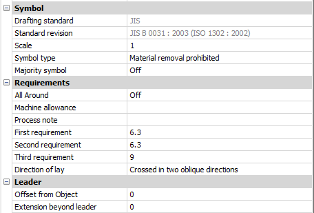
Note: The surface symbol properties depend on the used standard.
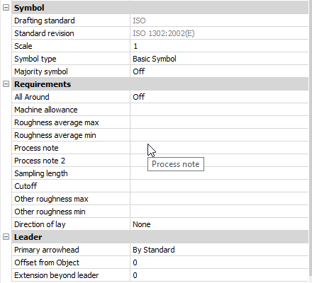
Symbol
- Symbol type
- Choose one of the following:
-
- Basic symbol

- Material removal required

- Material removal prohibited

- Basic symbol
- Majority symbol
- Indicates the common state of all surfaces using a single collective indication symbol.
Requirements
- All Around
- Toggles the visibility of the All Around surface texture in the symbol.
- Machine allowance
- Specifies the machining allowance for the surface.
- Process note
- Defines the process requirements for the surface.
- First requirement
- Defines the first requirement for the surface.
- Second requirement
- Defines the second requirement for the surface.
- Third requirement
- Defines the third requirement for the surface.
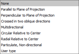
- Direction of lay
-
Sets the direction of lay for the surface.
-
- Roughness average max
- Defines the maximum roughness average for the surface.
- Roughness average min
- Defines the minimum roughness average for the surface.
- Process note2
- Defines the process requirements for the surface.
- Sampling length
- Defines the sampling length required for the surface.
- Other roughness max
- Defines the maximum other roughness for the surface.
- Other roughness min
- Defines the minimum other roughness for the surface.
Leader
- Offset from Object
- Specifies the distance between the extension line’s start point and the attached object.
- Extension beyond leader
- Specifies the distance between the symbol’s start point and the surface extension line’s end point.