AMWELDSYM command
Creates a welding symbol.

Icon: ![]()
Method
Select the entity to attach the welding symbol and specify the points for its location. The Weld Symbol dialog box opens, where you can customize the weld symbol.
- Esistono due casi d'uso per attivare le entità meccaniche:
-
- Quando si crea un nuovo disegno che contiene entità meccaniche:
- Impostare la variabile di sistema LOADMECHANICAL2D su ON (1).
- Iniziare un nuovo disegno utilizzando un modello Mechanical2d.
- Quando si apre un disegno che contiene entità meccaniche:
- Impostare la variabile di sistema LOADMECHANICAL2D su ON (1).
- Aprire un disegno ACM esistente e avviate la creazione di simboli speciali.
- Quando si crea un nuovo disegno che contiene entità meccaniche:
Note: Queste quote sono compatibili con l'applicazione legacy AutoCAD® Mechanical.
Note: Le quote verranno aggiunte al layer AM_5.
Note: Dopo l'apertura di un disegno contenente entità meccaniche, il riempimento di altri disegni con dati correlati al meccanico verrà eseguito on-demand in contrasto con le versioni precedenti. Questo sarà possibile quando un utente copia le entità relative al meccanico nel disegno "vanilla". In caso di copia, entità che non sono correlate ai dati meccanici, un disegno "vanilla" non verrà riempito con dati meccanici.
Note: Quando si apre un disegno che contiene entità meccaniche, ma la variabile di sistema LOADMECHANICAL2D è impostata su OFF, sulla barra di stato viene visualizzato un fumetto di avviso che descrive la situazione e fornisce un collegamento ipertestuale per abilitare e caricare immediatamente i moduli 2D di Mechanical.
After creating the symbol prototype with the AMWELDSYM command, you can configure the exact welding symbol's properties from the Properties panel:
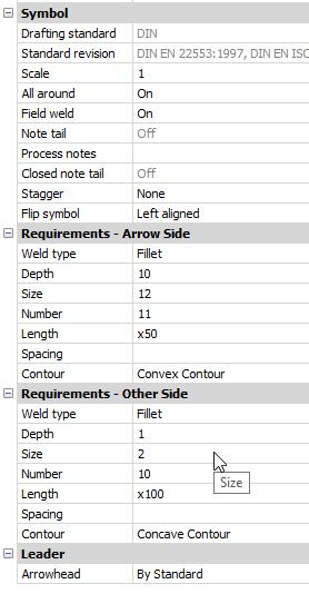
- Symbol
-
- All Around
- Toggles the visibility of the All Around symbol in the welding symbol.
- Field weld
- Toggle the visibility of the Field weld symbol in the welding symbol.
- Note tail
- Displays the state of the note tail.
- Process notes
- Defines the process notes.
- Closed note tail
- Defines the closed note tail.
- Stagger
- Chooses between move and mirrored stagger for intermittent welds on both sides.
- Flip symbol
- Chooses between left and right aligned for weld symbol.
- Requirements - Arrow side
-
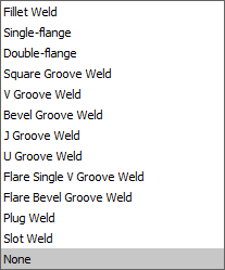
- Weld type
- Defines the weld type from the options below:
-
- Depth
- Defines the groove depth of the weld.
- Size
- Defines the size of the weld.
- Length
- Defines the length of the weld.
- Spacing
- Defines the spacing dimension for intermittent weld.
- Contour
- Defines the shape of the weld.
- Requirements - other side
- Defines the type and dimensions of the weld on the other side.
- Leader
- Defines the default arrowhead type for welding symbols.