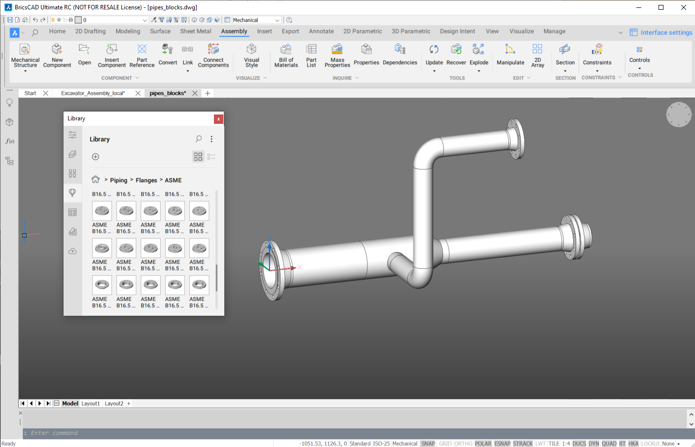
Rurociągi w projektowaniu złożeń
Przegląd

Bezszwowe i spawane rury, kolanka, trójniki, krzyżaki, reduktory i kołnierze są szeroko stosowane w przemyśle maszynowym, motoryzacyjnym i lotniczym. Występują również w przemyśle naftowo-gazowym, chemicznym i wodociągowym. BricsCAD® posiada bibliotekę parametrycznych części rurociągów zgodnych z różnymi normami, takimi jak ASME, DIN i ISO. Te standardowe części są parametryczne. Możesz łatwo dostosować ich parametry, powiązać je z różnymi parametrami globalnymi i użyć ograniczeń 3D, aby prawidłowo połączyć części. BricsCAD® umożliwia usprawnienie tych rutynowych operacji przy użyciu trybu inteligentnego polecenia BMWSTAW i dedykowanego polecenia BMPOŁĄCZ.
Umieść części rurociągu w złożeniu
Przeciągnij i upuść dowolną znormalizowaną część rurociągów z panelu Biblioteka do zespołu.
- Kopiuje wyrażenia parametrów tej części do odpowiednich parametrów wstawianej części.
- Dodaje zestaw wiązań 3D w celu połączenia części.
Ręczne tworzenie wiązań 3D między standardowymi częściami orurowania
Standardowe części rurociągów mają zestaw elementów szkieletu (punktów i linii) na warstwie STD_PARTS_PIPING_CONNECTION, która jest domyślnie wyłączona.
Ograniczanie dopasowania
- 2 punkty armatury, które powinny się pokrywać
- 2 linie złączek, które powinny być współliniowe.
Wiązanie rury
Powiązanie rur jest bardziej złożone, ponieważ rura może mieć dowolną długość. Jeśli rura jest już powiązana ze złączką z jednej strony za pomocą 2 współbieżnych wiązań 3D, wówczas wiązanie z drugiej strony musi być inne.
- Wiązanie zgodności 3D między linią, która reprezentuje oś rury, a odpowiadającą jej linią drugiej złączki,
- Oparte na geometrii wiązanie odległości 3D między płaską powierzchnią rury po przeciwnej (już związanej) stronie a odpowiednim punktem łącznika, który jest łączony.
Następnie należy wpisać nazwę ograniczenia odległości w polu wyrażenia dla parametru Długość rury. Ponieważ więzy oparte na geometrii umożliwiają sterowanie określonym wymiarem, rura zawsze będzie miała prawidłową długość, a taka parametryzacja nie ograniczy dalszej edycji złożenia przy użyciu bezpośredniej manipulacji dodatkowymi wiązaniami wymiarowymi niezwiązanymi z geometrią.
Automatyczne łączenie części rurowych
Zestaw wiązań jest tworzony automatycznie przy użyciu trybu inteligentnego polecenia BMWSTAW lub dedykowanego polecenia BMPOŁĄCZ w celu połączenia 2 standardowych części.
Tworzenie zestawienia materiałów dla złożenia rurowego
W zestawieniu komponentów możesz chcieć, aby wszystkie rury tego samego typu i rozmiaru (numer części), ale o różnych długościach, były wymienione jako ta sama część
Użyj funkcji agregującej w Menadżerze BOM, aby połączyć wszystkie takie części w jednym wierszu z ich całkowitą długością.

