Reprezentacje
Przegląd
Użyj poleceń BMROZBIJ, BMPRZESUŃEKSPLODOWANE, BMLINIEŚLEDZENIA i WIDOKPODST.
Funkcje reprezentacji eksplodowanej (utworzonej za pomocą polecenia BMROZBIJ) i sekwencji (utworzonej za pomocą polecenia BMSEKWENCJA) tworzą asocjacyjne reprezentacje zespołów i nie modyfikują samego zespołu. Reprezentacje są przechowywane w dedykowanych blokach, które można edytować i wstawiać zgodnie z własnymi potrzebami. Z reprezentacji można również generować widoki rysunków.
Reprezentacje są asocjacyjne. Każda część w reprezentacji jest połączona z odpowiadającą jej częścią w zespole. Użyj polecenia BMBALONY, aby zaktualizować rozwinięte reprezentacje do bieżącego stanu zespołu, a także umieścić adnotacje w dymkach na odpowiednich widokach rysunku.
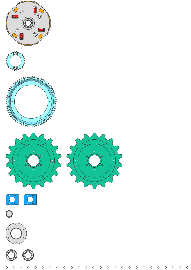
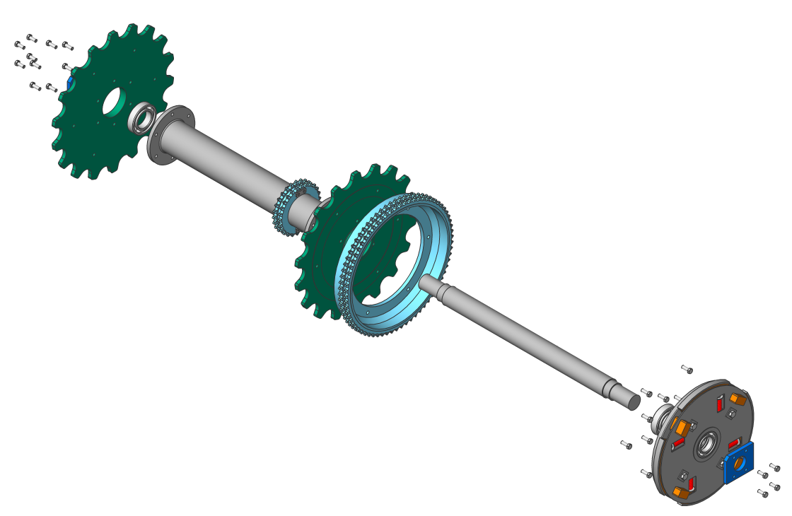
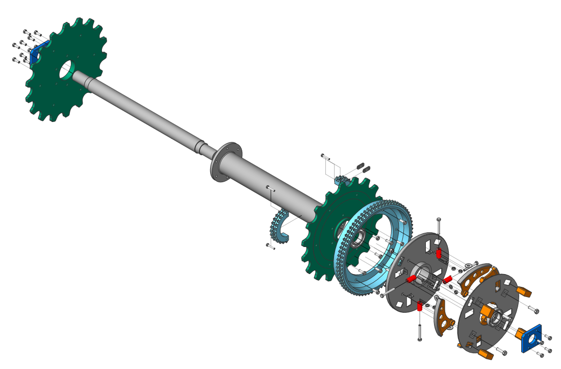
Przykład Rozstrzelonej Reprezentacji
Poziomy Rozwiniętej Reprezentacji
Reprezentacje zawierają odniesienia do komponentów.
Obsługiwane są 2 poziomy reprezentacji: Góra i Dół.
-
Górny poziom:
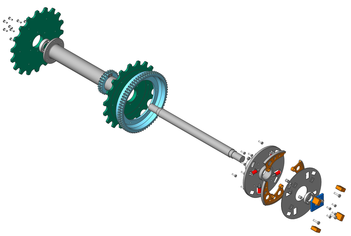
Reprezentacja zawiera odniesienia tylko do komponentów najwyższego poziomu. Komponenty najwyższego poziomu to komponenty wstawiane bezpośrednio do głównego zespołu. Komponent najwyższego poziomu w reprezentacji nie jest dalej eksplodowany - wszystkie jego części i podzespoły pozostają zmontowane. Reprezentacja najwyższego poziomu pozwala zobaczyć podstawowy skład zespołu.
-
Dolny poziom:
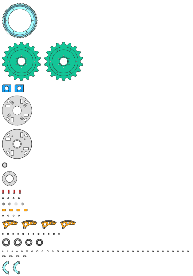
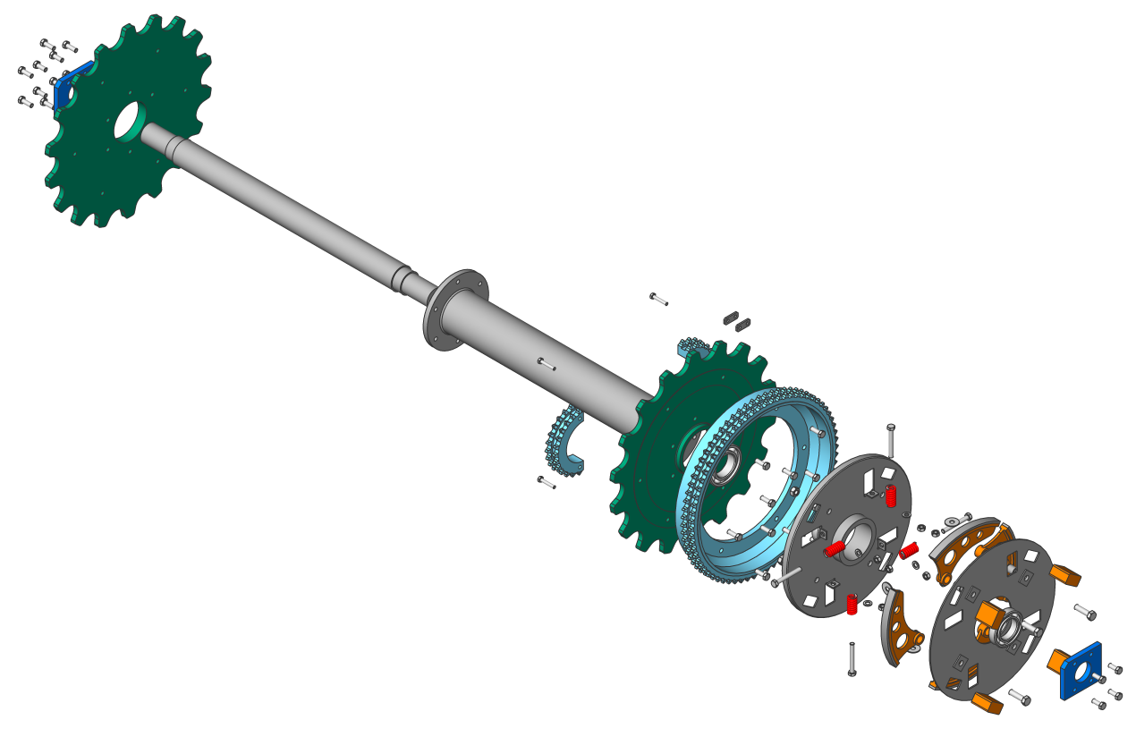
Reprezentacja zawiera odniesienia tylko do komponentów najniższego poziomu. Komponenty najniższego poziomu to części końcowe, które nie zawierają innych części lub podzespołów. Reprezentacje na najniższym poziomie pozwalają zobaczyć wszystkie części w izolacji.
Algorytmy
BricsCAD udostępnia 3 algorytmy do automatycznego tworzenia reprezentacji oraz algorytm ręczny.
| Algorytm | Opis |
|---|---|
| Tabela według typu | Utwórz eksplozję podobną do tabeli, w której komponenty tego samego typu są zgrupowane w wierszach. |
| Liniowy | Znajdź sekwencję demontażu komponentów w danym kierunku i uporządkuj komponenty. Uwaga: Uwzględnia to możliwe fizyczne kolizje między komponentami. Komponenty mogą być przenoszone przez algorytm tylko wtedy, gdy nie ma innych komponentów (jeszcze nie przeniesionych), które je blokują.
|
| Automatycznie | Znajdź sekwencję demontażu komponentów w odniesieniu do hierarchii montażu. Uwaga: Uwzględnia to wszystkie możliwe kolizje fizyczne. Dla każdej części lub podzespołu kierunek ruchu jest identyfikowany automatycznie.
|
| Ręcznie | Utwórz dokładną kopię zespołu gotową do niestandardowej edycji. W tym trybie można utworzyć niestandardową reprezentację bez zmiany głównego zespołu. |
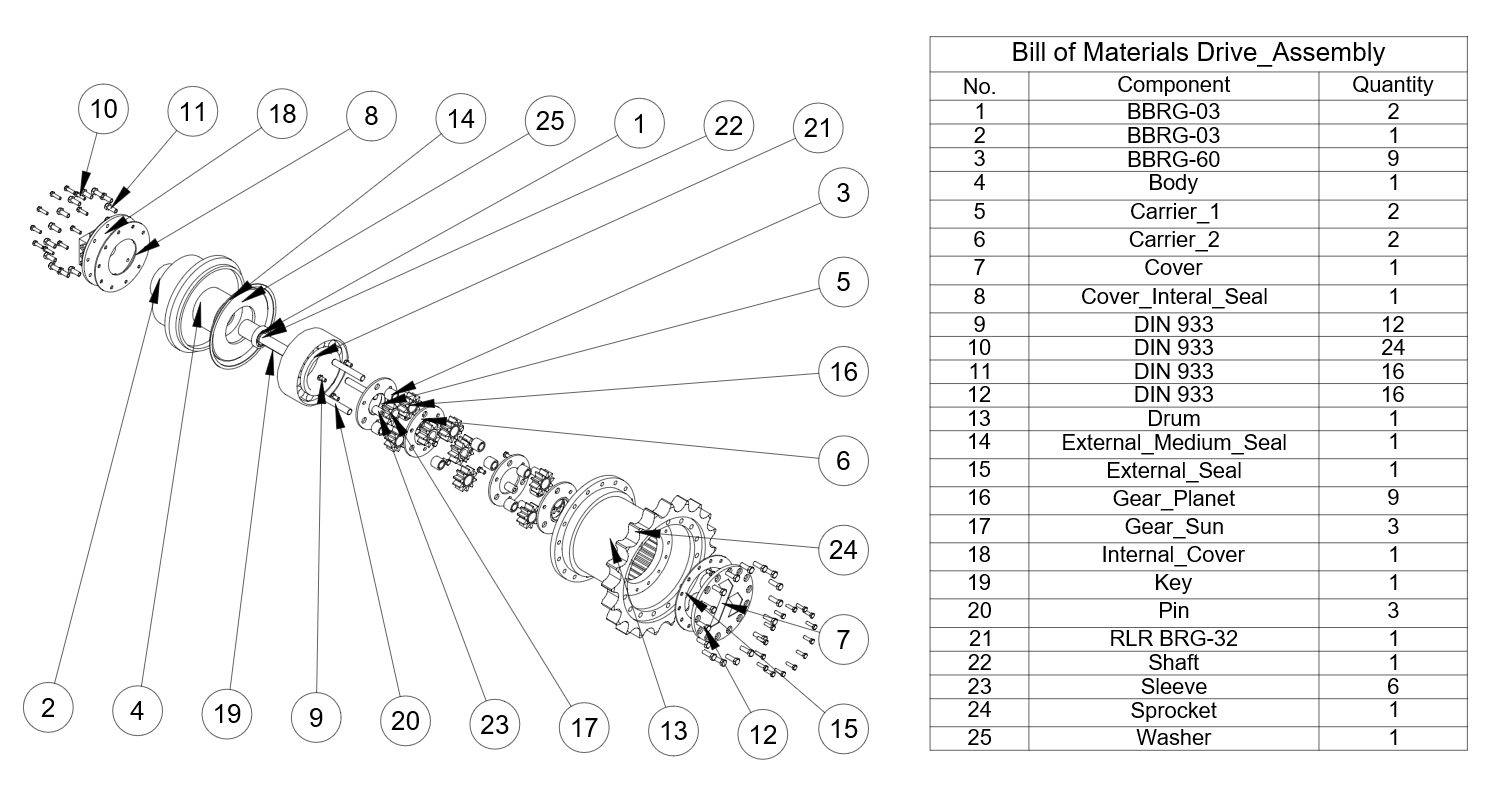
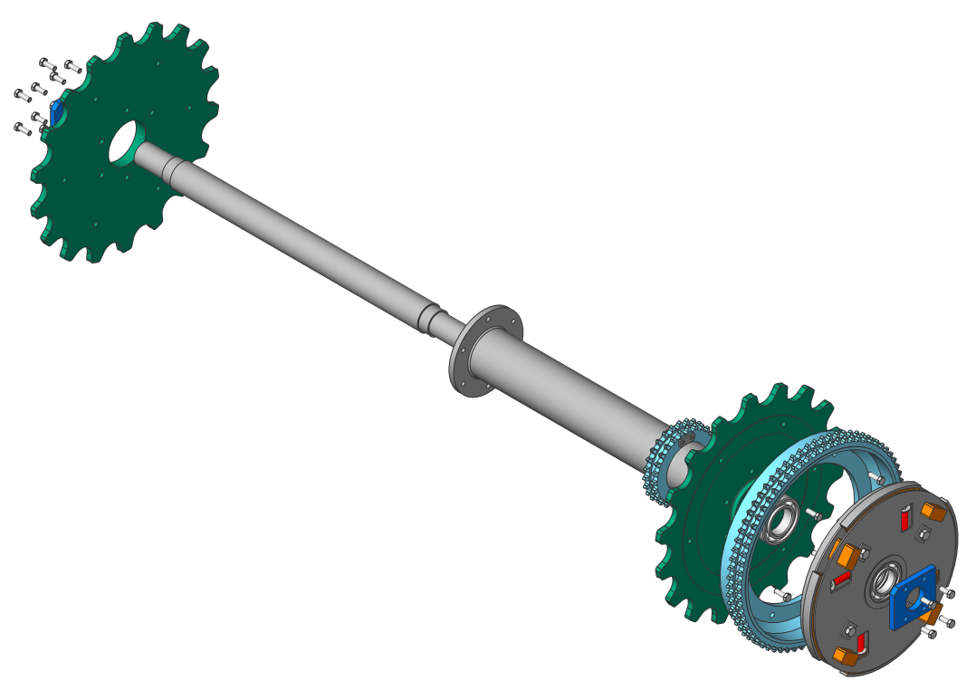
Przykład: Zespół głównego wału napędowego
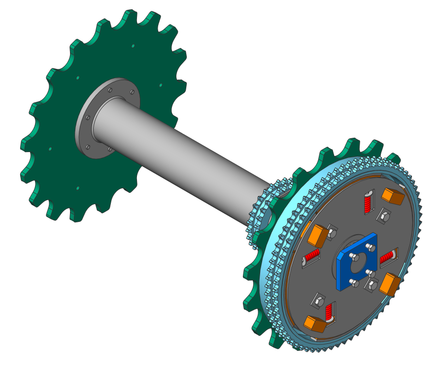
Przykład: zespół głównego wału napędowego
| Tabela według typu | Liniowy | Automatycznie | |
|---|---|---|---|
| Górny poziom |
|
|
|
| Dolny poziom |
|
|
|
Kroki i animacje
Reprezentacje mogą zawierać jeden lub kilka kroków, które opisują konkretną sekwencję montażu lub demontażu. Każdy krok odpowiada zestawowi komponentów, które muszą zostać przeniesione na tym konkretnym etapie w celu złożenia lub demontażu głównego zespołu. Wszystkie algorytmy reprezentacji automatycznie tworzą wszystkie wymagane kroki. Możesz także usuwać, scalać, dzielić, przenosić lub dodawać dodatkowe kroki.
Każdy krok ma unikalną nazwę, której można użyć do opisania kroku.
Możliwe jest animowanie konkretnego kroku, jak również całej sekwencji kroków, zarówno w kierunku bezpośrednim, jak i odwrotnym (w celu uzyskania animacji demontażu i montażu). Aby animacja działała poprawnie, w reprezentacji musi być obecny początkowy krok, który definiuje początkowy stan zespołu. Użyj właściwości Auto ukryj reprezentacji, aby automatycznie ukryć komponenty, które nie są ważne dla danego kroku podczas animacji.
Edycja reprezentacji
Każda reprezentacja jest przechowywana jako blok. Umożliwia to edycję reprezentacji za pomocą edytora bloków.
Aby otworzyć reprezentację do edycji:
- Kliknij prawym przyciskiem myszy wymaganą reprezentację w przeglądarce Przeglądarka Mechaniczna.
- Wybierz Edytuj z menu kontekstowego.Edytor bloków otworzy się automatycznie.Uwaga: Reprezentację można otworzyć do edycji, klikając ją dwukrotnie.
Gdy reprezentacja jest otwarta do edycji, można zmienić stan kroku na bieżący krok, klikając go dwukrotnie.
Użyj poleceń MBPRZESUŃ, PRZESUŃ, MBOBRÓĆ i BMPRZESUŃEKSPLODOWANE, aby przesunąć komponenty wewnątrz reprezentacji do wymaganych pozycji. Polecenie BMPRZESUŃEKSPLODOWANE automatycznie dodaje wszystkie niezbędne kroki po bieżącym kroku. W przypadku innych operacji należy zapisać bieżący krok po zakończeniu edycji. Zapisywana jest tylko różnica między bieżącym i poprzednim krokiem.
Możliwe jest również powiązanie adnotacji tekstowych (polecenie MTEKST) i dowolnych elementów innych niż części zespołu z wybranym krokiem. Te adnotacje i encje będą widoczne tylko w wybranych krokach i będą ukryte, gdy inne kroki będą aktywne; jednak ich pozycje nie są przechowywane w krokach.
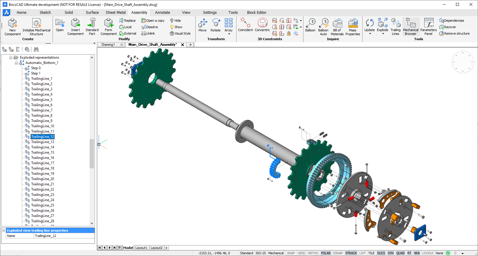
Linie naprowadzające
Linie śledzenia pomagają wyjaśnić relacje między częściami. Jest to polilinia 3D, która reprezentuje trajektorię i wyświetla ruch części podczas procesu demontażu.
Przykład linii końcowych
Użyj polecenia BMLINIEŚLEDZENIA, aby dodać końcowe linie do reprezentacji, która jest otwarta do edycji. Narzędzie to tworzy wszystkie linie końcowe. W tym celu wykorzystywane są informacje z kroków widoku rozłożonego.
Linie końcowe można wygenerować dla wszystkich części, dla podzbioru części lub dla każdego kroku. W przypadku podzbioru linie końcowe zostaną utworzone tylko dla części z tego podzbioru, chociaż dodane zostaną tylko niezbędne linie końcowe. Niektóre części mogą w ogóle nie mieć linii końcowych. Możesz także ręcznie wybrać 2 części, aby dodać linię końcową między nimi. Linia końcowa dla kroku będzie wyświetlana tylko dla tego kroku.
Gdy obliczana jest linia końcowa, algorytm automatycznie określa lokalizację części i lokalizację, z której część została usunięta w celu obliczenia trajektorii. Uwzględnia ruchy obu części.
Każda linia końcowa jest wyświetlana w panelu Przeglądarki Mechanicznej. Za pomocą panelu Przeglądarki Mechanicznej można zobaczyć wszystkie linie końcowe w modelu; podświetlić, wybrać i powiększyć części połączone z wybraną linią; zmienić nazwę lub usunąć linię końcową.
Końcowe linie można edytować za pomocą standardowych narzędzi edycji polilinii 3D.
Widok rozstrzelony właściwości linii końcowej
Utwórz reprezentację
- Wybierz jedną z poniższych akcji, aby uruchomić polecenie BMROZBIJ:
-
Kliknij przycisk narzędzia Rozbij
 na panelu Narzędzia zakładki Złożenie.
 -
Kliknij przycisk narzędzia Rozbij
na pasku narzędzi Złożenie. -
Wybierz Rozbij w menu Złożenie.
-
Wpisz BMROZBIJ w wierszu poleceń.
-
- Jeśli ma to zastosowanie, ustaw Poziom i Ustaw nazwę rozwiniętej reprezentacji za pomocą opcji Ustawienia.
- Wybierz algorytm.Pasek poleceń wyświetli: Wybierz zachowanie widoku rozbitego [Edytuj/Generuj widoki rysunku/Zakończ]:
- Wybierz jedną z proponowanych akcji:
- Wybierz Edytuj, aby edytować rozwiniętą reprezentację.
- Wybierz Generuj widoki rysunkowe, aby wygenerować widoki rysunkowe rozwiniętej reprezentacji.
- Wybierz Zakończ, aby zakończyć polecenie.
Generowanie widoków rysunkowych reprezentacji
- Uruchom polecenie WIDOKPODST.Pasek poleceń wyświetli: Wybierz obiekty lub [Cały model/Ustwienia wstępne/Widoki specjalne] <Cały model>:
- Wybierz opcję Widoki specjalne.Zostanie wyświetlony monit: Wybierz widok [Widok Rozstrzelony /Widok Rozłożony/Powrót]:
- Wybierz opcję Rostrzelony widok.Pojawi się okno dialogowe wyboru reprezentacji i kroku.
- Wybierz reprezentację.Pasek poleceń wyświetli: Wprowadź nową lub istniejącą nazwę arkusza, aby uczynić bieżącym <Arkusz1>:
- Jeśli ma to zastosowanie, wprowadź Nazwę Układu dla reprezentacji.
- Umieść wygenerowane widoki rysunku reprezentacji w układzie przestrzeni papieru.
Aktualizacja reprezentacji
Uruchom polecenie BMAKTUALIZUJ lub opcję Aktualizuj polecenia BMROZBIJ, aby zsynchronizować reprezentacje z bieżącym stanem złożenia.
Jeśli ma to zastosowanie, dostosuj reprezentację. Takie korekty mogą być wymagane ze względu na dodanie i/lub usunięcie niektórych części.
Zarządzanie reprezentacje
Zarządzanie reprezentacje
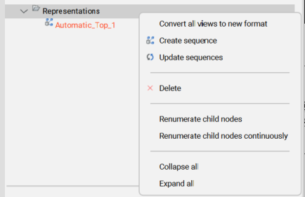
Otwórz przeglądarkę Przeglądarka Mechaniczna, aby zobaczyć wszystkie reprezentacje w dokumencie. Wszystkie reprezentacje i sekwencje będą wymienione w grupie Reprezentacje. Otwórz menu kontekstowe dla wybranych reprezentacji, aby zobaczyć wszystkie obsługiwane operacje w tym kontekście:
Każdy widok eksplodujący ma zestaw właściwości. Niektóre właściwości można edytować.
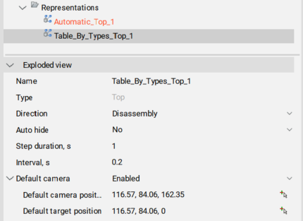
| Właściwość | Opis |
|---|---|
| Nazwa | Nazwa reprezentacji. Musi on być unikalny dla wszystkich reprezentacji, a także dla wszystkich bloków w modelu. |
| Typ | Typ reprezentacji: Góra lub Dół. |
| Kierunek | Kierunek animacji. Wybierz: Demontaż (od początku do końca) lub Montaż (od końca do początku). |
| Auto ukryj | Jeśli ustawiona na Tak, wszystkie nieistotne części dla danego kroku zostaną ukryte podczas animacji. |
| Czas trwania kroku, s | Domyślny czas trwania każdego kroku podczas animacji (w milisekundach). Domyślną wartością jest 1000, co odpowiada 1s czasu trwania. |
| Interwał, s | Domyślny interwał między krokami w milisekundach. |
| Domyślna kamera | Ustawia domyślną akcję kamery. Jeśli opcja Włącz, używa domyślnej pozycji kamery i celu dla wszystkich kroków, w których opcja Kamera jest ustawiona jako domyślna. Jeśli Wyłączone, używa pozycji kamery i celu poprzedniego kroku dla kroku, który ma Kamera ustawione jako domyślne. |
Operacje na reprezentacjach
Obsługiwane operacje zależą od tego, czy reprezentacja jest otwarta do edycji.
Jeśli reprezentacja jest nie otwarta do edycji, możliwe są następujące operacje:

| Operation | Opis |
|---|---|
| Edycja | Otwiera reprezentację do edycji. Uwaga: Jeśli skonfigurowano, używana jest kamera niestandardowa bieżącego kroku. W przeciwnym razie, jeśli jest włączona, używana jest domyślna kamera widoku eksplozji, a jeśli nie, używana jest bieżąca kamera.
Wskazówka: Reprezentację można również edytować za pomocą polecenia BEDYCJA lub klikając ją dwukrotnie.
|
| Aktualizuj | Synchronizuje reprezentacje z bieżącym stanem zespołu. |
| Konwertuj do nowego formatu | Konwertuje starą reprezentację formatu na nową. Uwaga: Ta opcja jest dostępna tylko wtedy, gdy na rysunku znajdują się reprezentacje w starym formacie.
|
| Generuj widoki | Generuje widoki dla reprezentacji. |
| Usuń | Usuwa reprezentację i powiązany blok z dokumentu. |
| Przelicz węzły podobne | Ponownie wylicza węzły reprezentacji. Każda grupa węzłów o identycznych nazwach będzie miała własną numerację. |
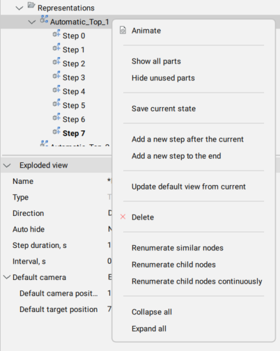
Jeśli reprezentacja jest otwarta do edycji, możliwe są następujące operacje:
| Operation | Opis |
|---|---|
| Animuj | Animuje całą sekwencję kroków. |
| Pokaż wszystkie części | Pokazuje wszystkie części w kroku. |
| Ukryj nieużywane części | Ukrywa nieużywane części przed krokiem. |
| Zapisz stan aktualny | Zapisuje bieżące pozycje części w bieżącym kroku. |
| Dodanie nowego kroku po bieżącym | Dodaje nowy krok po bieżącym. Uwaga: Nowy krok zostanie automatycznie ustawiony jako Aktualny. Wszystkie niezapisane modyfikacje rozwiniętej reprezentacji zostaną utracone.
|
| Dodaj nowy krok na końcu | Dodaje nowy krok po ostatnim. Uwaga: Nowy krok zostanie automatycznie ustawiony jako Aktualny. Wszystkie niezapisane modyfikacje rozwiniętej reprezentacji zostaną utracone.
|
| Zaktualizuj domyślny widok z bieżącego | Aktualizuje domyślną pozycję kamery, która jest powiązana z samym widokiem eksplozji, a nie z krokiem początkowym. Możliwe jest posiadanie niestandardowej kamery dla kroku początkowego i kamery domyślnej, które są różne. |
| Usuń | Usuwa reprezentację i powiązany blok z dokumentu. |
| Przelicz węzły podobne | Ponownie wylicza węzły reprezentacji. Każda grupa węzłów o identycznych nazwach będzie miała własną numerację. |
| Przelicz węzły podrzędne | Ponownie wylicza podobne węzły kroku bieżącej reprezentacji. |
| Wyliczanie węzłów podrzędnych w sposób ciągły | Ponownie wylicza wszystkie węzły kroku bieżącej reprezentacji pomimo nazw. |
Ponadto wszystkie kroki zostaną wymienione w Przeglądarce Mechanicznej dla tej reprezentacji.
Zarządzanie krokami reprezentacji
Otwórz Przeglądarkę Mechaniczną i otwórz wymaganą reprezentację do edycji. Wszystkie kroki zostaną wyświetlone pod odpowiednim węzłem w drzewie.
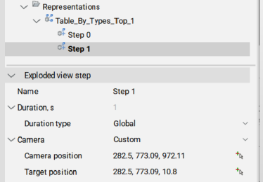
Właściwości kroków
| Właściwość | Opis |
|---|---|
| Nazwa | Nazwa kroku. Musi być unikalny dla tej reprezentacji. |
| Czas trwania, s | Czas trwania kroku. Domyślnie jest on równy czasowi trwania kroku ustawionemu dla reprezentacji. |
| Typ czasu trwania | Określ, czy czas trwania musi być pobrany z reprezentacji, czy też jest specyficzny dla tego konkretnego kroku. |
| Wartość czasu trwania, s (tylko dla typu bezwzględnego czasu trwania) | Czas trwania tego kroku w sekundach. |
| Kamera | Pozycja kamery: Domyślnie:
|
| Pozycja kamery (tylko dla kamery niestandardowej) | Wyświetlanie pozycji kamery. Naciskając ikonę po prawej stronie, użytkownik może zmienić pozycję kamery. |
| Pozycja docelowa (tylko dla kamery niestandardowej) | Wyświetlanie docelowej pozycji kamery. Naciskając ikonę po prawej stronie, użytkownik może zmienić pozycję docelową. |
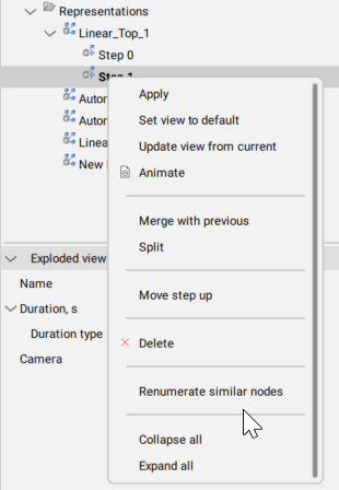
Operacje na krokach
| Operation | Opis |
|---|---|
| Zastosuj | Ustaw krok jako bieżący i zaktualizuj części w reprezentacji zgodnie z tym krokiem. Uwaga: Dwukrotne kliknięcie kroku daje ten sam efekt.
|
| Ustaw widok na domyślny | Ustawienie pozycji kamery dla bieżącego kroku. Ta pozycja kamery będzie używana jako domyślna orientacja dla wygenerowanych widoków dla bieżącego kroku. Jeśli z krokiem nie jest powiązana żadna konkretna pozycja kamery, odziedziczy on pozycję kamery z kroku początkowego. W przypadku nowo utworzonych widoków rozstrzelonych, początkowy krok otrzyma tę samą pozycję kamery, co model. |
| Zaktualizuj widok z bieżącego | Aktualizacja pozycji kamery dla bieżącego kroku. |
| Animuj | Animacja kroku. |
| Scal z poprzednim | Połącz ten i poprzedni krok. Poprzedni krok jest usuwany. |
| Podziel | Podziel krok na sekwencję kroków, z których każdy odpowiada dokładnie jednej części. |
| Przesuń stopień w górę | Przesuń stopień o jedną pozycję wyżej w drzewie. |
| Przesuń krok niżej | Przesuń krok o jedną pozycję w dół w drzewie. |
| Usuń | Całkowicie usuń stopień, a także związane z nim ruchy części. Następnie pozycje części są aktualizowane w rozwiniętej reprezentacji. |
| Przelicz węzły podobne | Ponownie wylicza węzły kroku. Każda grupa węzłów o identycznych nazwach będzie miała własną numerację. |
Edycja reprezentacji
- Wybierz reprezentację w Przeglądarce Mechanicznej.
- Kliknij prawym przyciskiem myszy rozwiniętą reprezentację i wybierz Edytuj z menu kontekstowego.Uwaga: Alternatywnie można uruchomić polecenie BEDYCJA i wybrać blok z rozwiniętą reprezentacją.
- Wykonaj niezbędne operacje, aby uzyskać pożądaną reprezentację.
- Zapisz bieżący krok.
- Zapisz zmiany za pomocą polecenia BZAMKNIJ z opcją Zapisz.
Dodaj końcowe linie
- Otwórz reprezentację do edycji.
- Uruchom polecenie BMLINIEŚLEDZENIA.
- Wybierz podzbiór części, dla których mają zostać utworzone linie końcowe, lub wybierz cały model.
- Wybierz punkty części, które mają zostać użyte do utworzenia trajektorii: początek lub środek.
- Jeśli ma to zastosowanie, edytuj wynikowe linie końcowe.
- Zapisz zmiany.