Okno dialogowe ustawień wizualnych
Otwiera się przez polecenie BIMMODELANALITYCZNY
Okno dialogowe Ustawienia wizualne umożliwia zaznaczanie i odznaczanie różnych cech osi i węzłów w celu podświetlenia (na żółto) osi i węzłów pasujących do tych cech. Możesz także zmienić rozmiar dysków reprezentujących węzły.
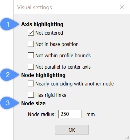
- Podświetlanie osi
- Podświetlanie węzłów
- Rozmiar węzła
Podświetlanie osi
Określa, kiedy/jak oś jest podświetlana.
- Nie wyśrodkowany
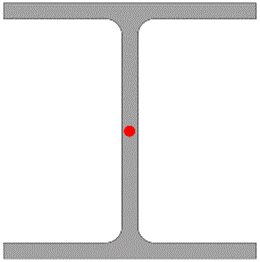
- Podświetla każdą oś, która nie znajduje się w środku liniowej bryły.
- Czerwona kropka oznacza środek profilu:
- Osie belek są zaznaczone na żółto, ponieważ osie górnych belek nie znajdują się w środku belki, ale na jej górnej krawędzi.
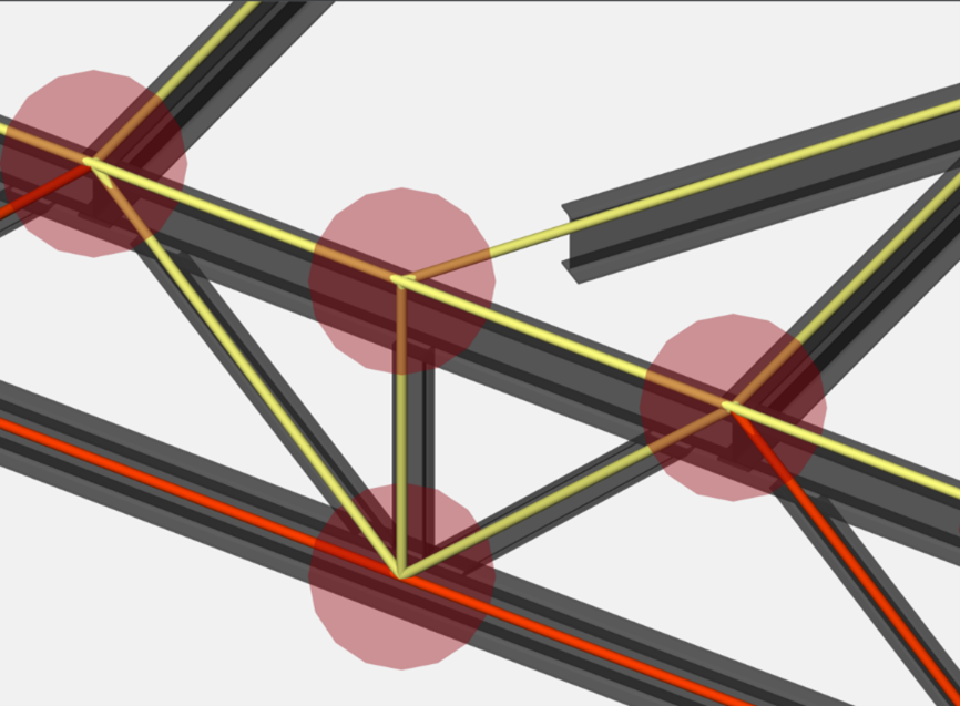
- Czerwona kropka oznacza środek profilu:
- Nie w pozycji podstawowej
- Podświetla każdą oś, która nie znajduje się w jednej z pozycji bazowych bryły liniowej.
- Czerwone kropki oznaczają podstawowe pozycje profilu:
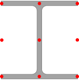
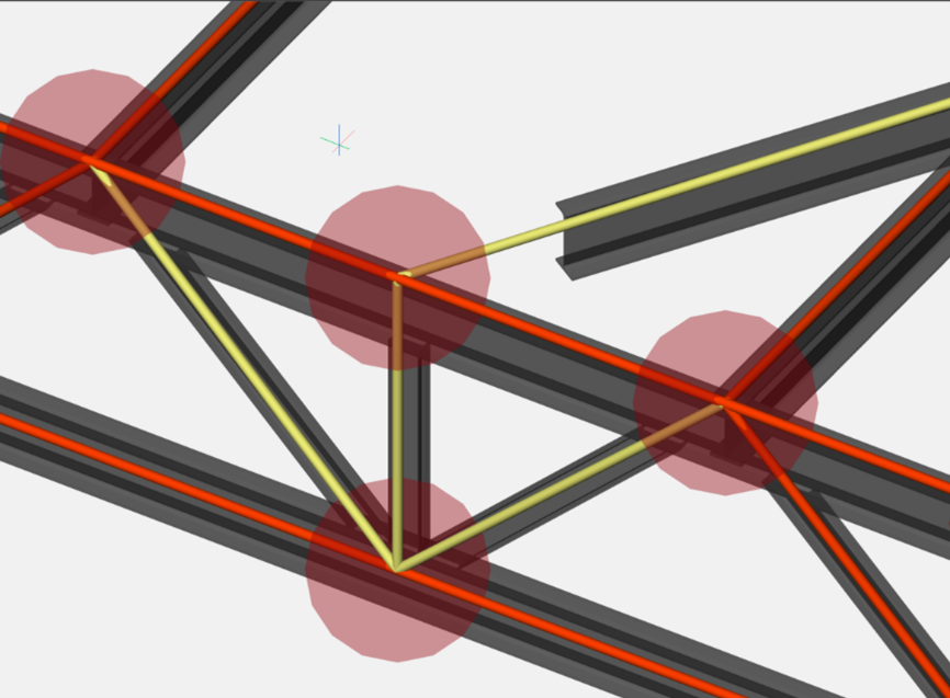
- Czerwone kropki oznaczają podstawowe pozycje profilu:
- Nie w granicach profilu
- Podświetla wszystkie osie znajdujące się poza granicami profilu.
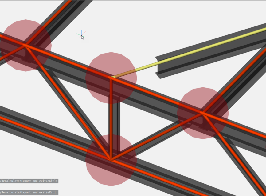
- Nie równolegle do osi środkowej
- Podświetla wszystkie osie, które nie są równoległe do osi środkowej.
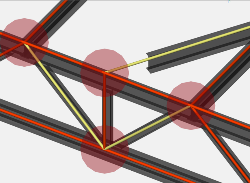
Podświetlanie węzłów
Określa, kiedy/jak węzły są podświetlane.
- Prawie pokrywa się z innym węzłem
- Podświetla wszystkie węzły, które prawie pokrywają się z innym węzłem.
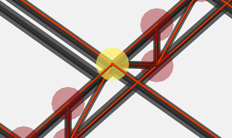
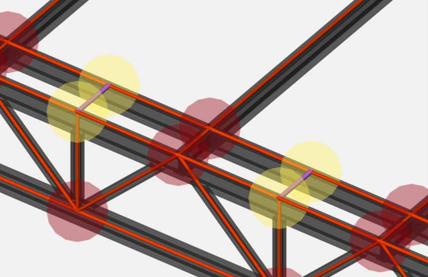
- Ma sztywne łącza
- Podświetla wszystkie węzły, które mają sztywne połączenia. Zobacz fioletowe linki na obrazku:
Rozmiar węzła
Określa charakterystykę rozmiaru węzła.
- Promień węzła:
- Węzły w modelu analitycznym są zaznaczone za pomocą wypełnionego okręgu. Określ rozmiar węzłów, wprowadzając promień węzła.
- Promień węzła: 150 mm
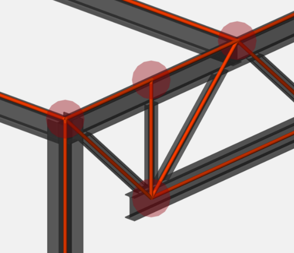
- Promień węzła: 350 mm
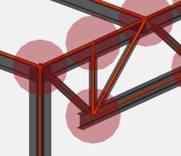
- Promień węzła: 150 mm

