Korzystanie z więzów geometrycznych
Wiązania Geometryczne:
- Określ relację geometryczną między 2 elementami (wspólnymi, koncentrycznymi, współliniowymi, równoległymi, prostopadłymi, stycznymi, gładkimi, symetrycznymi, równymi).
- Określ stały kąt (poziomy, pionowy).
- Określ stałe położenie (fix).
Gdy wiązanie geometryczne jest stosowane do elementu:
- Położenie elementu jest dostosowywane zgodnie z zastosowanym wiązaniem.
- Obok elementu wyświetlana jest ikona wskazująca zastosowane wiązanie. Jeśli zostanie zastosowanych wiele więzów geometrycznych, ikony zostaną połączone na pasku więzów.
Tworzenie więzów geometrycznych
Narzędzia do tworzenia więzów wymiarowych znajdują się w:
- Pasek narzędzi Wiązania 2D .
- Kartę Wstążce parametryczne.
- Wiązania 2D menu podręcznym menu parametrycznego.
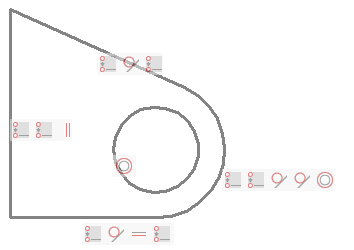
Na poniższym obrazku:
- Punkty końcowe trzech linii i łuku są połączone wiązaniami zbieżności.
- Punkt środkowy okręgu i łuku są koncentryczne.
- Dwie linie muszą być styczne do łuku.
- Jedna linia ma wiązanie pionowe (= równoległe do osi Y bieżącego układu współrzędnych), jedna linia ma wiązanie poziome (= równoległe do osi X bieżącego układu współrzędnych).
Wyświetlanie pasków wiązań
Paski więzów są ukrywane, gdy rysunek jest zamykany i ponownie otwierany.
Narzędzia do sterowania wyświetlaniem pasków więzów znajdują się na:
- Pasek narzędzi Wiązanie geometryczne .
- Karta wstążki parametrycznych.
- Pokaż/Ukryj wiązania 2D menu podręcznym menu parametrycznego.
Narzędzia te wykonują polecenie PASEKWIĘZÓW przy użyciu określonej opcji.
Dostępne opcje to:
- Pokaż/Ukryj: monit o wybranie elementów.
- Pokaż wszystkie: pokaż wszystkie wiązania wymiarowe na rysunku.
- Ukryj wszystkie: ukryj wszystkie więzy wymiarowe na rysunku.
- Wartość zmiennej systemowej CONSTRAINTBARDISPLAY steruje widocznością więzów geometrycznych:
- Wyświetla paski wiązań gdy wiązania geometryczne są dodane.
- Wyświetl ukryte wiązania wymiarowe przy wyborze obiektów z wiązaniami.
- Po najechaniu kursorem na element z wiązaniem wymiarowym niebieski znacznik wiązania (
 ) jest wyświetlany, jeśli zmienna systemowa SELECTIONPREVIEW jest ustawiona na 1 lub 3 lub gdy Quad jest aktywny.
Sterowanie położeniem paska więzów
Domyślnie paski znaczników więzów są tworzone blisko punktu środkowego elementu i są utrzymywane w tym względnym położeniu, gdy zmienia się położenie elementu. Pasek więzów można przeciągnąć w inne miejsce. To nowe położenie względne jest zachowywane do momentu, gdy opcja Resetuj polecenia PASEKWIĘZÓW przywróci domyślne położenie paska więzów.
Zmiana położenia paska wiązań
- Umieść kursor na pasku ograniczeń.
- Naciśnij i przytrzymaj lewy przycisk myszy, aby przesunąć pasek ograniczeń.
- Zwolnij lewy przycisk myszy w żądanym miejscu.
Przywracanie domyślnego położenia pasków więzów
-
Wykonaj jedną z następujących czynności:
- Kliknij narzędzie Pokaż/Ukryj wiązanie geometryczne.
- Uruchom polecenie PASEKWIĘZÓW.
Monituje: Wybierz Encje.
-
Wybierz elementy, a następnie kliknij prawym przyciskiem myszy lub naciśnij Enter.
BricsCAD® raportuje liczbę wybranych jednostek.
Monituje: Wybierz opcję dla wiązań [Pokaż/Ukryj/Resetuj] <Show> <Pokaż>:
-
Wykonaj jedną z następujących czynności:
- Wybierz Resetuj z menu kontekstowego.
- Wpisz R w wierszu polecenia, a następnie naciśnij Enter.
Praca z paskami wiązań
Sterowanie wiązaniem
- Przesuń kursor na ikonę wiązania.
- Zostanie wyświetlona etykietka narzędzia wskazująca typ wiązania.
- Skojarzona jednostka (lub jednostki) zostanie wyróżniona.
- Odpowiednia ikona na pasku więzów skojarzonego elementu zostanie podświetlona.
Usuwanie wiązania
- Przesuń kursor na ikonę wiązania na pasku ograniczeń.
- Kliknij prawym przyciskiem myszy, a następnie kliknij Usuń.
- Wiązanie zostanie usunięte, a ikona zostanie usunięta z paska więzów i z paska więzów skojarzonego elementu.
Ukrywanie paska ograniczeń elementu
Przesuń kursor na pasek ograniczeń, a następnie kliknij przycisk Zamknij (x).
Usuwanie wiązań
Aby usunąć wszystkie wiązania ze zbioru wskazań, należy:
-
Wykonaj jedną z następujących czynności:
- Kliknij narzędzie Usuń wiązania 2D.
- Uruchom polecenie USUŃWIĄZANIA.
Zostanie wyświetlony monit: Wybierz elementy, aby usunąć wszystkie wiązania:
- Wybierz elementy, z których chcesz usunąć wiązania.
- Kliknij prawym przyciskiem myszy, aby zatrzymać wybieranie elementów i usunąć wszystkie wiązania ze zbioru wskazań.
Kilka przykładów
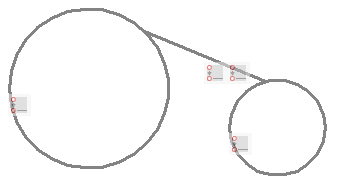
Wiązania zgodności między punktem końcowym linii a dwoma okręgami.
Jeśli punkty końcowe lub środkowe elementów już się pokrywają, opcja Automatyczne wiązanie polecenia ZGODNEWG automatycznie zastosuje wiązania pokrywania się do takich punktów.
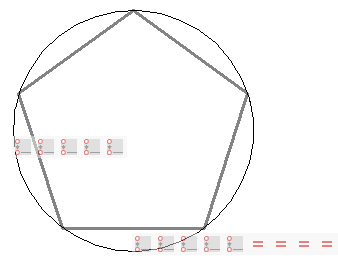
Stosując wiązania zgodności między wierzchołkami pięciokąta a okręgiem oraz równe wiązania między jednym bokiem a czterema pozostałymi bokami, promień okręgu definiuje rozmiar pięciokąta.
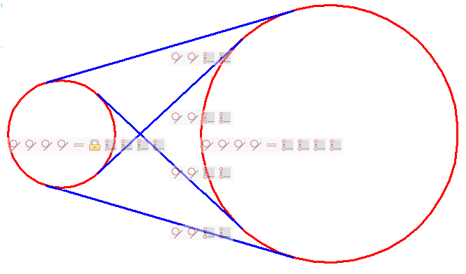
Wiązania zgodności między punktami końcowymi linii stycznych a okręgami zapobiegają wystaniu linii stycznych poza punkty styczne.
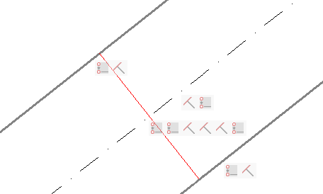
Wiązania zgodności są używane do:
- Wymuś położenie punktów końcowych czerwonej linii na pogrubionych liniach.
- Wymuś położenie środka czerwonej linii na linii kreska-kropka.
Pogrubione linie i linia kreska-kropka mają prostopadłe ograniczenie z czerwoną linią. W rezultacie linia kreska-kropka zawsze leży wyśrodkowana między dwiema pogrubionymi liniami.

