Praca z chmurami punktów
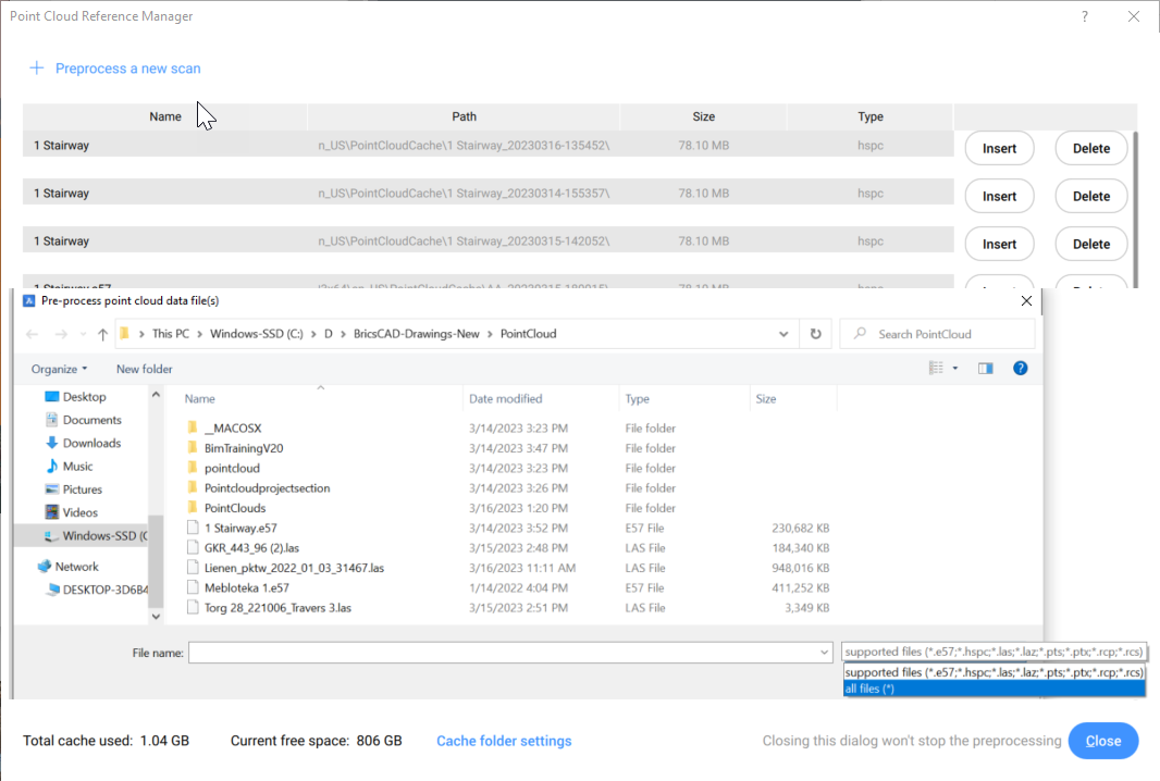
Przetwarzanie wstępne
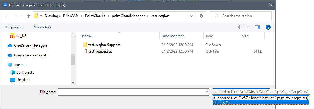
Aby wstępnie przetworzyć chmurę punktów, można użyć polecenia WSTAWCHMURĘPUNKTÓW lub wybrać opcję Przetwarzaj nową skanowania w Menedżerze odniesień chmury punktów, do którego można uzyskać dostęp za pomocą polecenia CHMURAPUNKTÓWODNIESIENIE.
Postęp wstępnego przetwarzania jest zapisywany w pliku dziennika w podfolderze powiązanym z chmurą punktów. Ten podfolder znajduje się wewnątrz bieżącej ścieżki pamięci podręcznej chmury punktów. Domyślna ścieżka dla bieżącej pamięci podręcznej chmury punktów to C:\Users\USERNAME\AppData\Roaming\Bricsys\BricsCAD\V23x64\en_US\PointCloudCache\Folder_for_processed_pointcloudi można ją ustawić w zmiennej systemowej POINTCLOUDCACHEFOLDER.
Wyrównanie
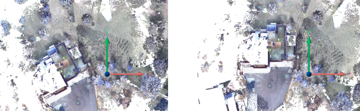
Polecenie PUNKTOBAWYRÓWNAJ automatycznie obraca chmurę punktów, aby optymalnie wyrównać ją z osiami X i Y, biorąc pod uwagę pionowe powierzchnie płaskie w chmurze punktów (np. ściany). Aby określić najlepszą linię trasowania, zostaniesz poproszony o określenie najbardziej odpowiedniego obszaru chmury punktów zawierającej ściany.
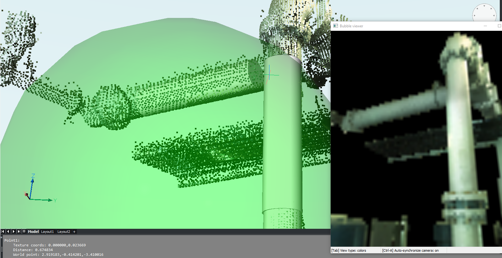
Przeglądarka bąbelków
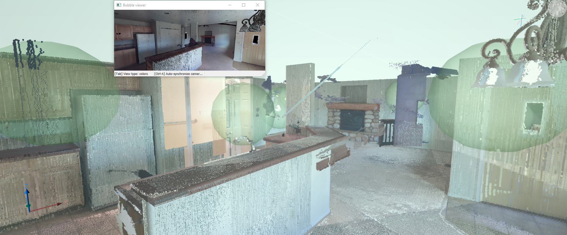
W zależności od oryginalnego formatu pliku chmury punktów i typu skanera używanego podczas skanowania, bąbelki (zielone kule) mogą być wyświetlane we wszystkich lokalizacjach skanowania.
W tych lokalizacjach doświadczysz najbardziej realistycznych reprezentacji wizualnych, otwierając przeglądarkę bąbelków.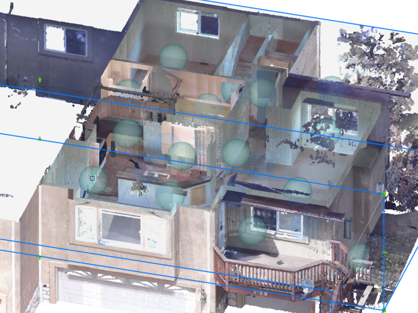
Wskaż indeks bąbelków w poleceniu POINTCLOUDBUBBLEVIEWER lub kliknij dwukrotnie jeden z bąbelków w obszarze modelu, aby otworzyć przeglądarkę bąbelków. Możesz nacisnąć środkowy przycisk myszy i przesunąć mysz, aby wyświetlić chmurę punktów w dowolnym kierunku z tego miejsca skanowania. Możesz także powiększać i pomniejszać za pomocą kółka myszy.
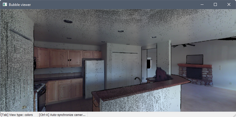
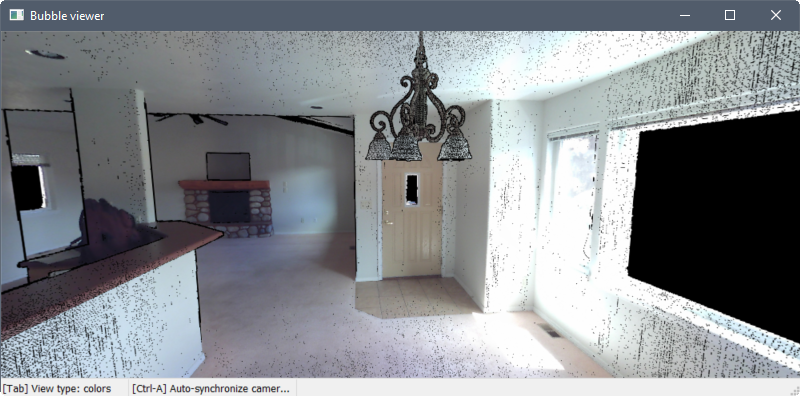
Naciśnij Tab, aby przełączać się między trzema różnymi trybami wizualnymi.
W pierwszym trybie punkty są wyświetlane jako ich rzeczywiste kolory lub w skali szarości, w zależności od sposobu skanowania danych.
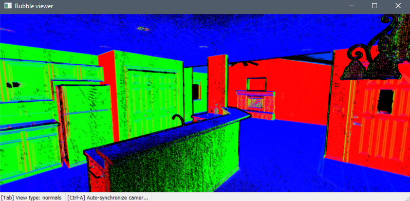
Drugi tryb wyświetla punkty jako czerwone, zielone lub niebieskie, zgodnie z ich normalnymi wektorami. Kolory odpowiadają osiom LUW.
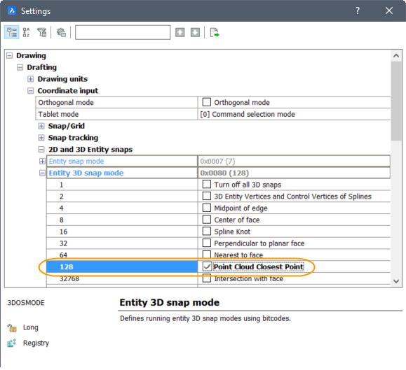
Punkty charakterystyczne
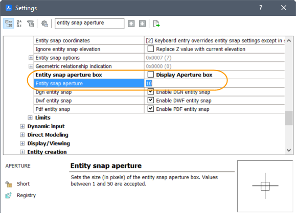
Włącz nowy punkt lokalizacji Closest Point chmury punktów wraz z innymi lokalizacjami 3D w menu, pasku narzędzi i ustawieniach Entity Snap.
Eksport
Polecenie CHMURAPUNKTÓWEKSPORT chmurę punktów umożliwia wyeksportowanie widocznych części chmury punktów do pliku PTS, HSPC lub LAZ.
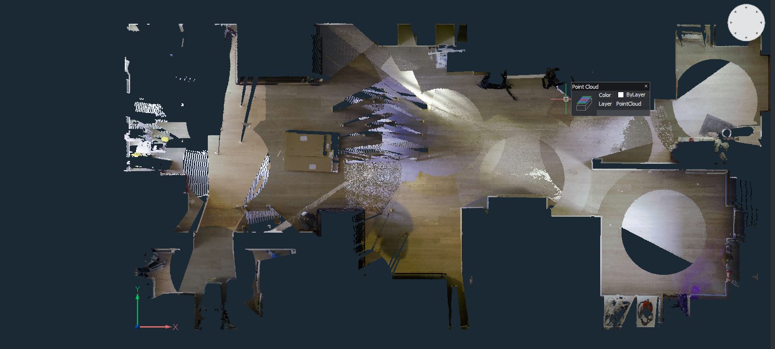
Wykrywanie podłogi
Rzutowanie chmury punktów
Planar Fit
Polecenie CHMURAPUNKTÓWDOPASUJPLANARNIE umożliwia tworzenie geometrii 3D na podstawie chmury punktów. Utworzy powierzchnię płaską lub bryłę po wybraniu punktu bazowego w chmurze punktów. Aby wykryć punkty, które leżą na tej samej płaszczyźnie co punkt bazowy, używana jest wartość progowa, którą można ustawić jako właściwość elementu chmury punktów. Przytrzymując przycisk Shift i wybierając sąsiednie ściany pomieszczenia, dopasowane płaszczyzny zostaną wydłużone/przycięte, tworząc zamkniętą powierzchnię.
- Wybierz otwory pozwala uwzględnić otwory drzwi i okien (tylko w przeglądarce dymków).
- Dopasuj obramowania umożliwia dopasowanie płaskiego konturu obramowania.
- Zszyj powierzchnie umożliwia zszycie wyniku wielu dopasowanych płaszczyzn na przykład w bryłę, która może być później użyta za pomocą polecenia BIMINVERTSPACE.
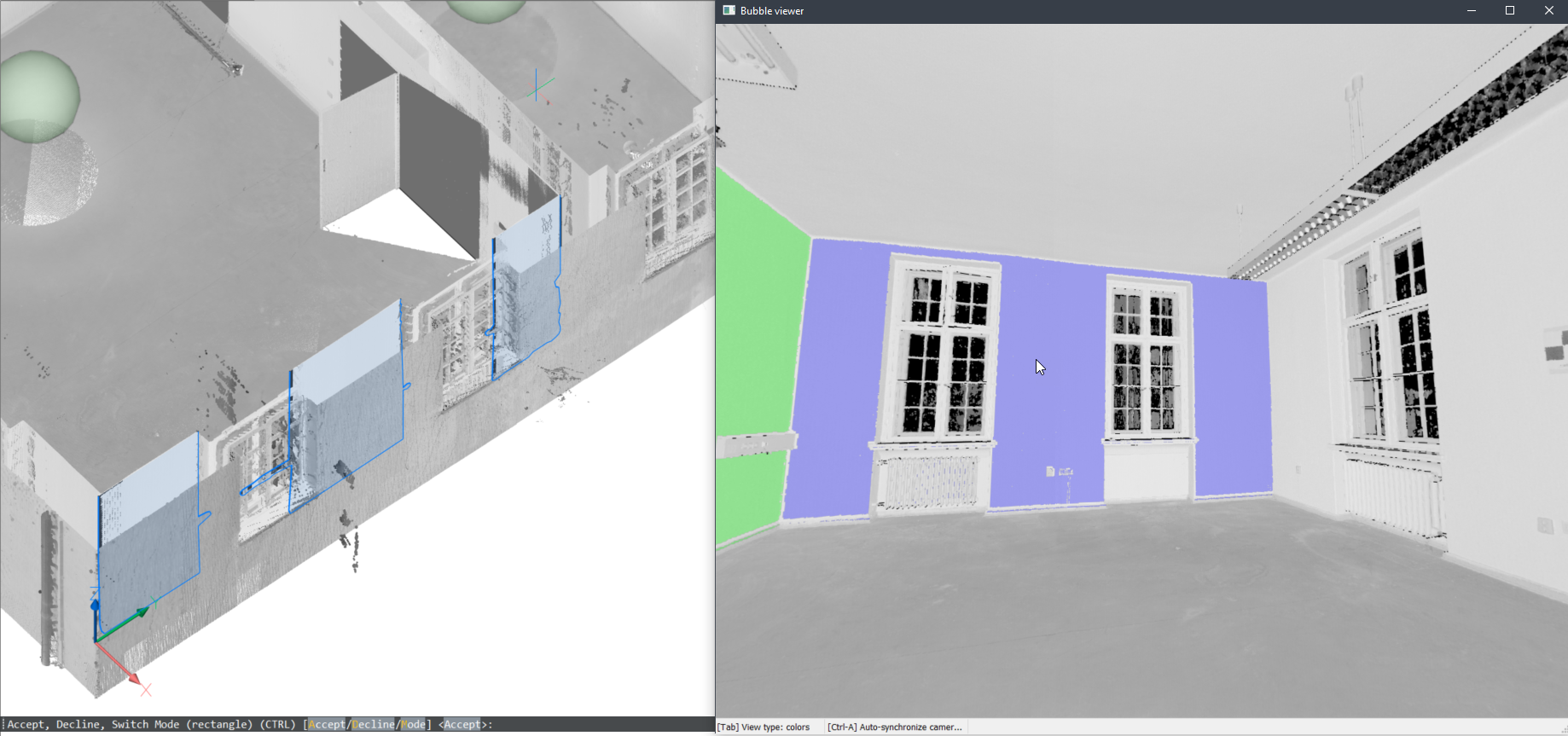
- W widoku bąbelkowym
-
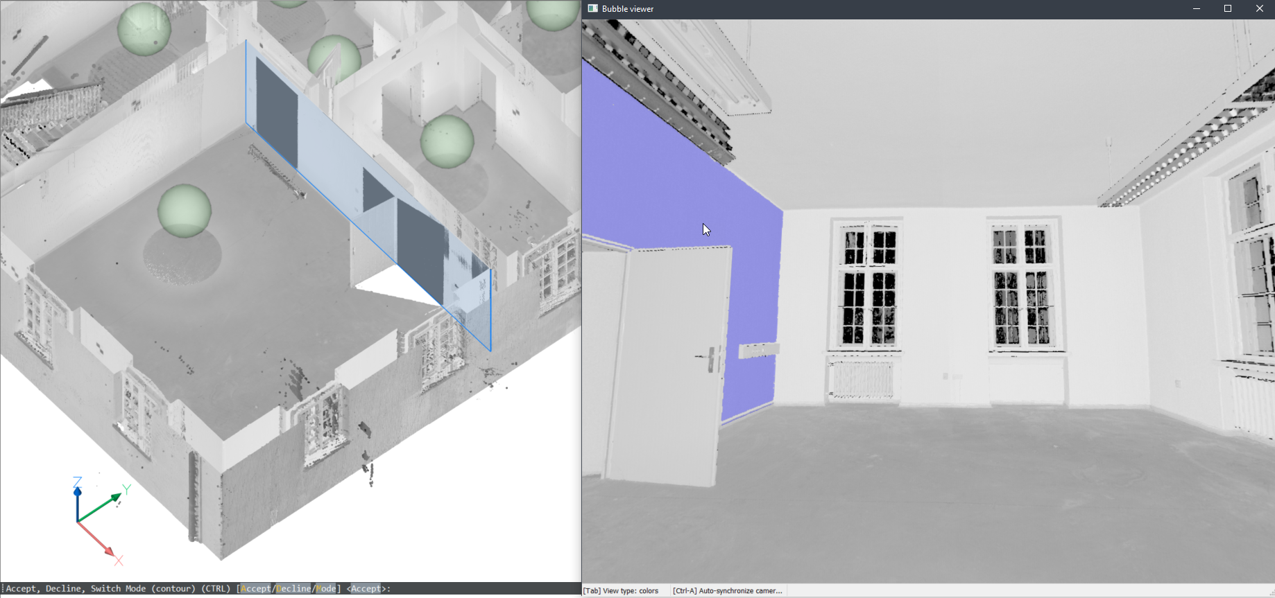
Jeśli przeglądarka bąbelków jest otwarta w momencie uruchomienia polecenia, BricsCAD oczekuje, że zostaną zaznaczone punkty początkowe płaszczyzny wewnątrz przeglądarki bąbelków. Kursor da ci podgląd normalnego kierunku samolotu. Następnie otrzymasz podgląd zarówno w przeglądarce bąbelków, jak i w widoku modelu. Możesz przełączać się między 2 reprezentacjami kształtów za pomocą CTRL.Note: Będąc nadal w trybie wyboru, odpowiednie punkty w dymku są wyświetlane na fioletowo. Punkty te są wyświetlane na zielono, gdy użytkownik zaakceptuje wygenerowany wynik.
- W obszarze modelu
-
Tego polecenia można również użyć w obszarze modelu, gdy przeglądarka bąbelków nie jest otwarta. BricsCAD poprosi o wybranie punktu chmury punktów w obszarze modelu. W zależności od rozmiaru widocznych części chmury punktów może to zająć więcej czasu w porównaniu z uruchomieniem polecenia w przeglądarce bąbelków. Ma to jednak dwie zalety, ponieważ przeszukuje wiele pozycji skanowania:
- Może tworzyć większe powierzchnie, łącząc części różnych skanów.
- Może wykrywać grubość ścian i płyt.
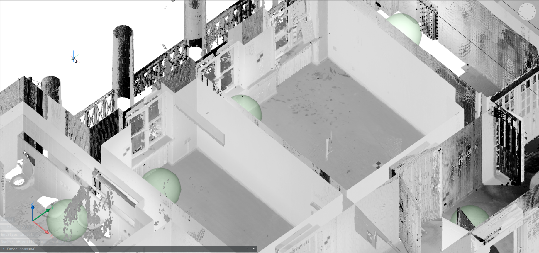
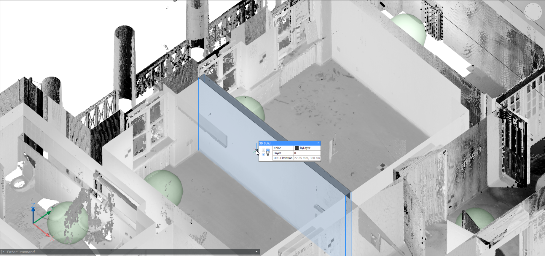
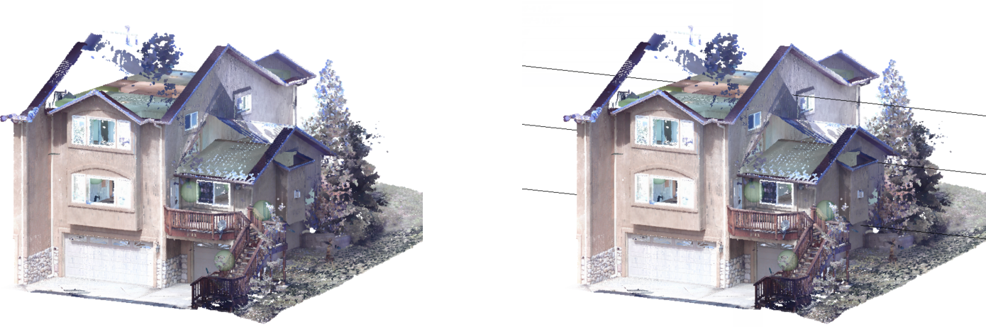
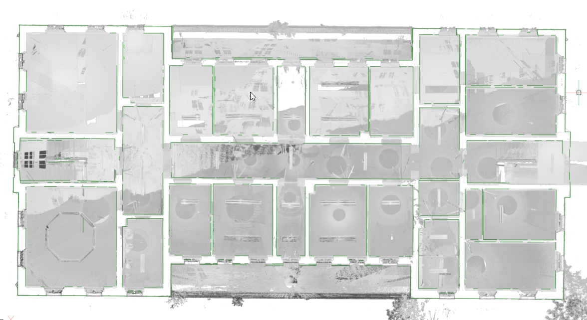
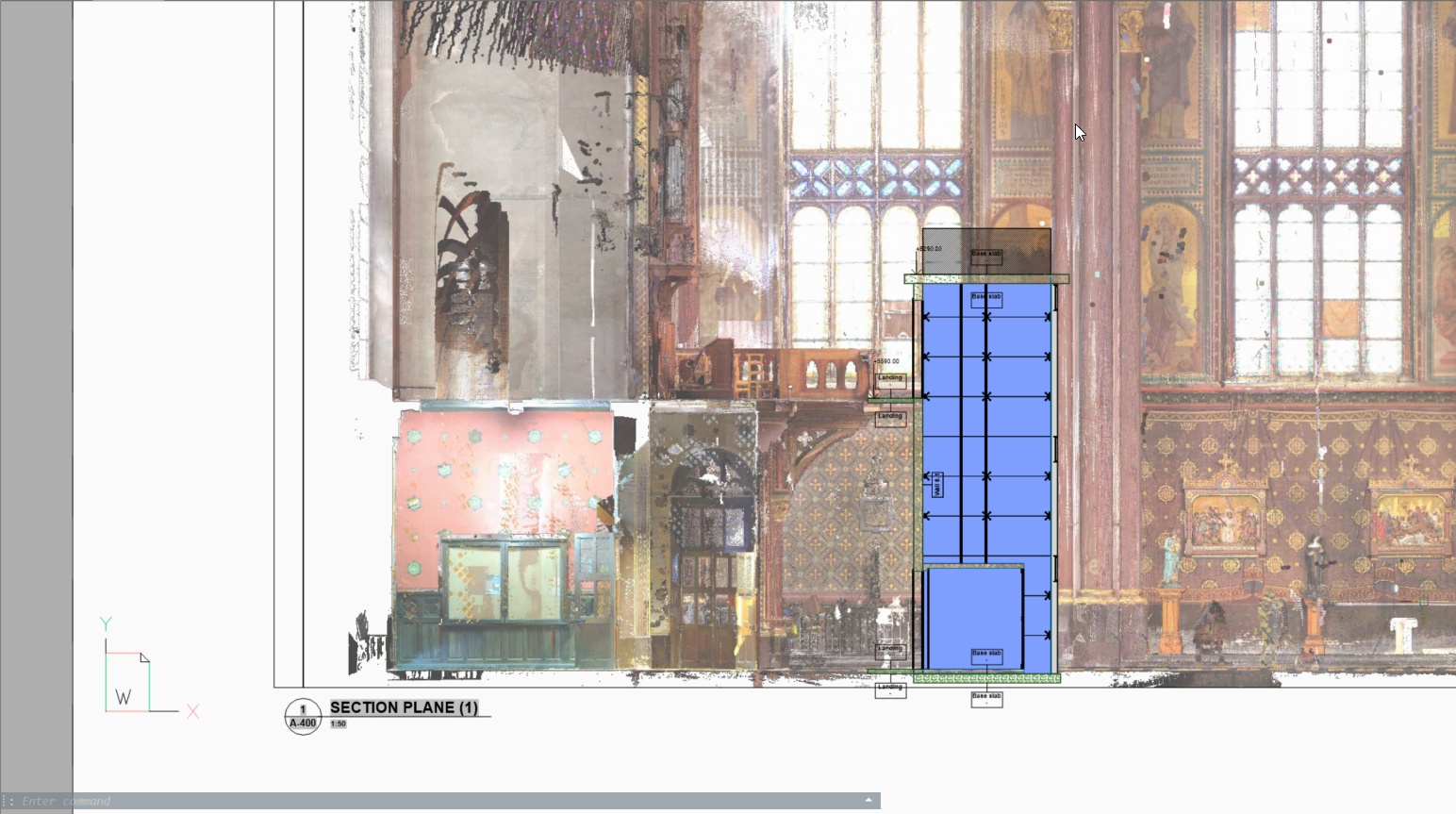
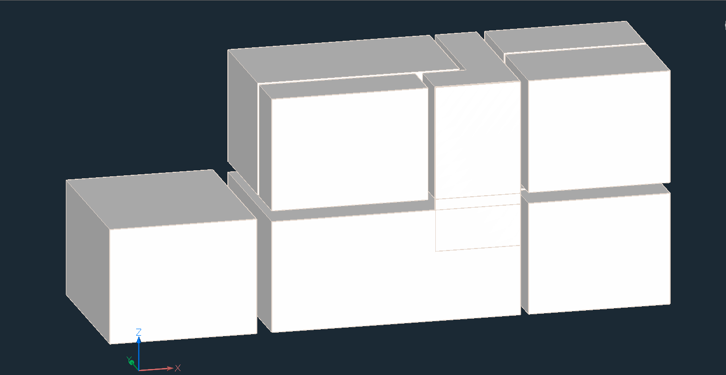
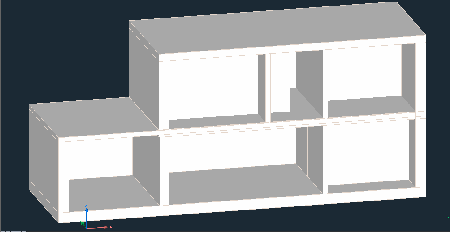
Note: W tym miejscu zapewniony jest przepływ pracy związany z konwersją skanu do modelu budynku. Chmura punktów (górny obraz) jest najpierw przekształcana w zestaw brył, po jednej na pomieszczenie, przy użyciu zszytych wyników CHMURAPUNKTÓWDOPASUJPLANARNIE (środkowy obraz). Polecenie BIMODWRÓĆPRZESTRZENIE przekształca te tymczasowe bryły pomieszczeń w model budynku ze ścianami i płytami z odwrócenia tych brył.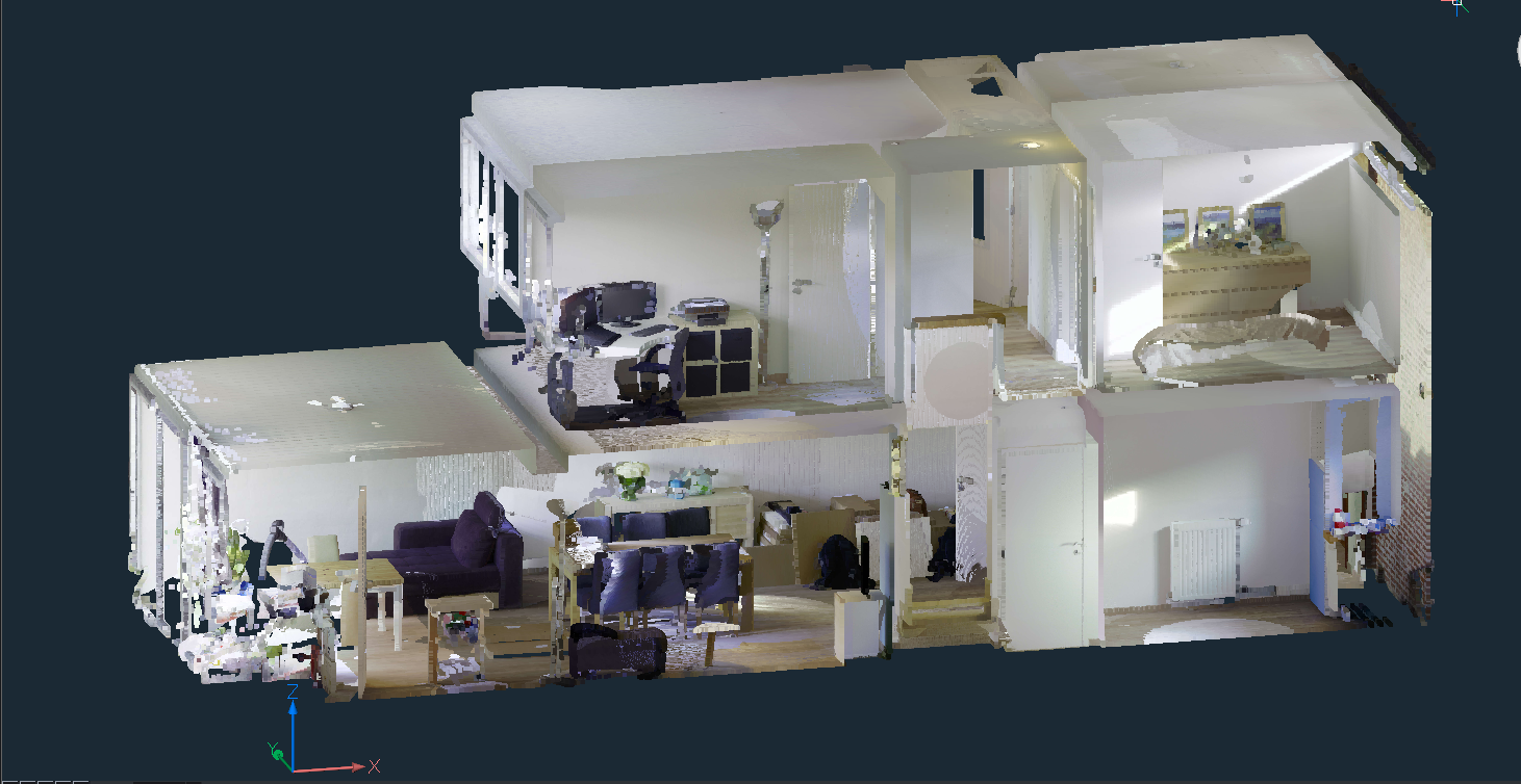
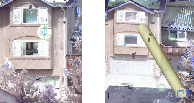
Dopasuj cylinder do bąbelków
CHMURAPUNKTÓWODCHYLENIE
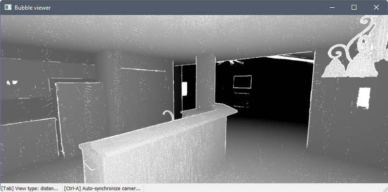
- CHMURAPUNKTÓWODCHYLENIE umożliwia wizualną ocenę dopasowania między strukturami płaskimi a punktami chmury punktów.
- Przekrój chmury punktów podłogi domu i płaszczyzny dopasowanej:
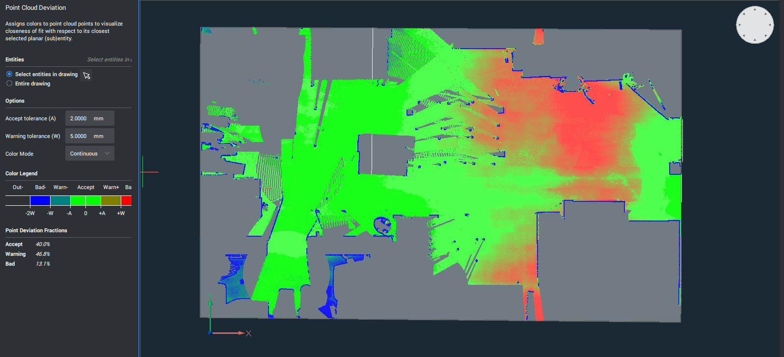
Odległości punktów od podłogi do płaszczyzny dopasowania są wizualizowane za pomocą mapy kolorów. W lewym panelu znajduje się wyjaśnienie kolorów (zielony jest płaski, gradient od zielonego do niebieskiego jest dalej nad płaszczyzną, gradient od zielonego do czerwonego znajduje się dalej poniżej płaszczyzny). Również podsumowanie procentów punktów, w których prezentowana jest kategoria (OK, poziom ostrzegawczy, ...)