Panel Menedżer parametrów
- Uruchom polecenie OTWÓRZPANELPARAMETRÓW.
- Kliknij prawym przyciskiem myszy panel wstążki lub pasek narzędzi i wybierz Menedżer parametrów z listy Panele.
Panel Menedżer parametrów jest głównym narzędziem do przeglądania i modyfikowania parametrów i ograniczeń w bieżącym rysunku.
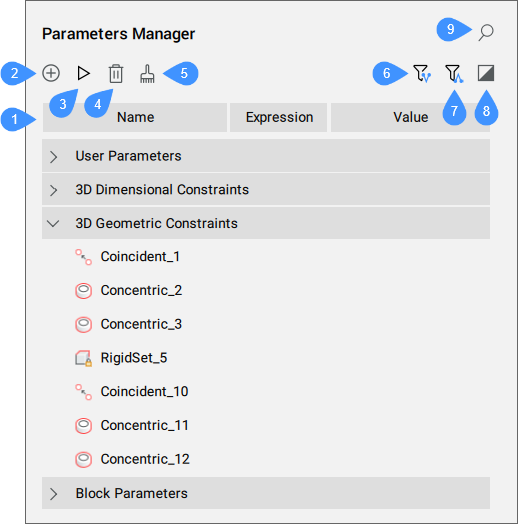
- Lista parametrów
- Nowy parametr
- Animuj
- Usuń
- Wyczyść nieużywane zmienne
- Pokaż parametry zależne
- Pokaż parametry definiujące
- Pokaż wybrane
- Szukaj
Lista parametrów
Wyświetla listę wszystkich parametrów na rysunku. Parametry są zorganizowane w rozszerzalnych kategoriach , które mogą obejmować parametry użytkownika (w tym te, które są powiązane z tabelami projektu ), wiązania wymiarowe 2D, wiązania wymiarowe 3D, parametry referencyjne, wiązania geometryczne 2D , wiązania geometryczne 3D, parametry bloków (komponentów) i parametry tablic.
Nagłówek listy parametrów zawiera kolumny reprezentujące właściwości parametrów. Kolumny można przesuwać do nowej pozycji, zmieniać ich rozmiar lub ukrywać. Parametry można uporządkować w kolejności rosnącej lub malejącej, naciskając określony nagłówek kolumny. Nagłówek listy parametrów ma domyślnie trzy kolumny: Nazwa, Wyrażenie i Wartość. Aby dodać więcej kolumn, kliknij prawym przyciskiem myszy nagłówek kolumn i wybierz żądane kolumny z listy:
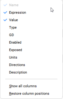
- Nazwa
- Wyświetla nazwę parametru.
- Wyrażenie
- Określa wyrażenie matematyczne parametru. Wyrażenie można edytować, klikając komórkę.
- Wartość
- Wyświetla wartość wynikającą z wyrażenia parametru. Wartość jest liczbą rzeczywistą tylko do odczytu, chyba że parametr jest powiązany z tabelą Projektową. W takim przypadku parametr ma listę możliwych wartości reprezentowanych jako pole combo. Wartość parametru można zmienić, wybierając nową wartość z listy. Pole kombi można przeszukiwać, wpisując podciąg wartości, aby szybko ją znaleźć. Jest to przydatne w przypadku dużych list wartości.
- Typ
- Wyświetla typ parametru:
- Typ wiązań dla wiązań (odległość, koncentryczne itp.).
- Typ parametru dla parametrów użytkownika i bloku (Rzeczywista, Ciąg).
- Typ parametru dla parametrów tablicowych (Rzeczywista, Boolowskie, Wyliczona).
- GD (sterowane geometrią)
- Jeśli WŁ, parametr jest sterowany geometrią.
- Dolna granica
- Określa dolną wartość parametru.
- Górna granica
- Określa górną wartość parametru.Uwaga: Górne i dolne granice są brane pod uwagę w operacjach dynamicznych, takich jak MBPRZESUŃ i OBRÓT3D.
- Włączony
- Określa, czy parametr wiązania geometrycznego jest brany pod uwagę.
- Narażone
- Określa, czy parametr jest widoczny i może być modyfikowany, gdy komponent jest wstawiony do zespołu.
- Jednostki
- Ustawia wymiar parametru. Do wyboru są: brak, liniowy (mm), kwadratowy (mm2) i sześcienny (mm3).
- Kierunki
- Określa kierunek dla parametru wiązania geometrycznego (dowolny, taki sam, przeciwny lub reset).
- Opis
- Umożliwia wpisanie opisu parametrów użytkownika.
Kliknięcie prawym przyciskiem myszy wybranego parametru otwiera określone menu kontekstowe, które zawiera tylko te opcje, które mają zastosowanie do tego elementu. Opcje te można również znaleźć w menu kontekstowym tego samego elementu w panelu Przeglądarka Mechaniczna.
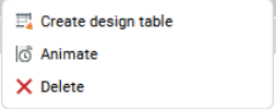
- Utwórz tabelę projektową
- Tworzy tabelę projektową do sterowania parametrami bloku parametrycznego.
- Animuj
- Animuje wartość parametru w określonym zakresie.
- Powiąż z parametrem
- Łączy parametr podkomponentu z parametrem poziomu głównego.
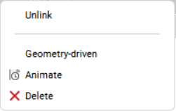
- Odłącz
- Przerywa powiązania między parametrem podkomponentu a parametrem poziomu głównego.
- Oparte na geometrii
- Jeśli zaznaczone, parametr jest sterowany geometrią.
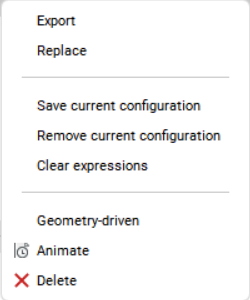
- Eksport
- Otwiera okno dialogowe Wybierz plik tabeli projektu w celu zapisania tabeli projektu.
- Zastąp
- Otwiera okno dialogowe Wybierz plik tabeli projektu w celu wybrania tabeli projektu, która zastąpi istniejącą.
- Zapisz aktualną konfigurację
- Zapisz aktualną konfigurację
- Usuń aktualną konfigurację
- Usuń aktualną konfigurację
- Wyczyść wyrażenia
- Usuwa formułę wyrażenia.
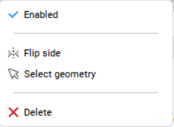
- Włączony
- Wyświetla i przełącza stan włączenia wiązania.
- Odwróć stronę
- Odwraca stronę wiązania.
- Zaznacz geometrię
- Wybiera podmioty zaangażowane w wybrane wiązania w przestrzeni modelu.
Nowy parametr
Wstawia nowy parametr użytkownika z wartościami domyślnymi dla Wyrażenia i Wartości.
Animuj
Animuje wybraną wartość parametru w określonym zakresie.
Usuń
Usuwa wybrane parametry i ograniczenia z rysunku.
Wyczyść nieużywane zmienne
Usuwa nieużywane zmienne.
Pokaż parametry zależne
Po włączeniu panel wyświetla parametry i wiązania w zależności od wybranych parametrów.
Pokaż parametry definiujące
Po włączeniu panel wyświetla parametry definiujące wybrany(e) parametr(y).
Pokaż wybrane
Po włączeniu panel wyświetla parametry i wiązania dla obiektów aktualnie wybranych w przestrzeni modelu lub wszystkich obiektów, jeśli nic nie jest wybrane.
Szukaj
Filtruje listę parametrów, aby wyświetlić tylko nazwy parametrów pasujące do ciągu znaków wprowadzonego w polu wyszukiwania.

