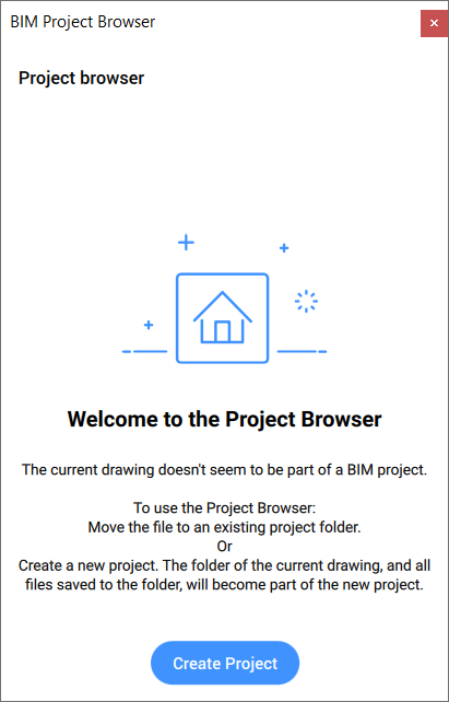
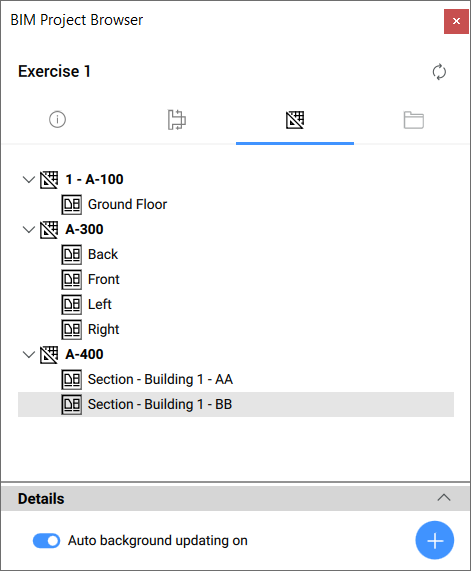
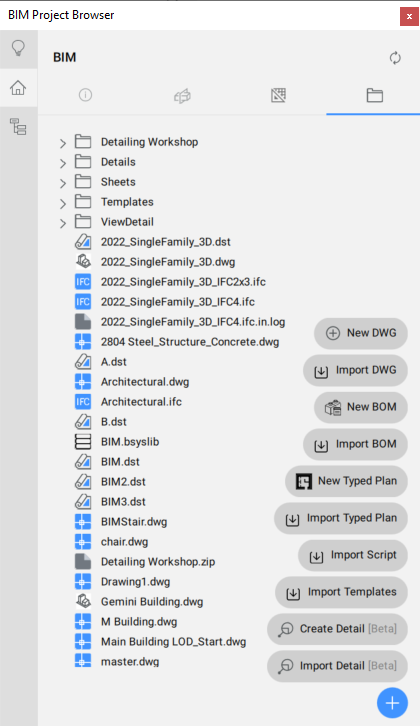
The BIM Project Browser panel offers a central location to manage all files and views in your BIM project.
Note: If the Project Browser doesn't display, right-click the Ribbon and select Panels > BIM Project Browser.
Once a new drawing is saved, you can press the Create Project button.
Note: When starting BricsCAD BIM, you can also create a new project from the Start tab by pressing the New project button.
When you save the new drawing in an existing project folder, the BIM Project Browser displays the Add to Project button. Click it to add the drawing and all it's necessary files that don't yet exist to the project folder.
During project creation, some files are automatically generated in the project folder, such as a sheetset file (DST), a database file (BSYSLIB) and a default sheet template (DWT). A new subfolder for the sheet templates is generated as well. Other files can be added manually to the project folder or can be generated later on.
Note: The folder in which the active drawing is stored becomes the project folder. All other files and subfolders of this folder will be considered part of this project.
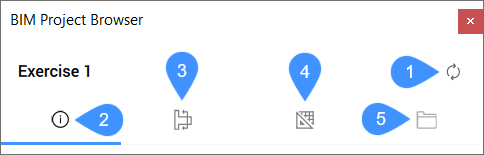
The BIM Project Browser panel consists of four tabs and a refresh button:
Refresh project
Info tab
Sections and views tab
Sheets tab
Files tab
Refresh project
Refreshes the BIM Project Browser panel to match changes in all BIM project (for example, Xref in the master drawings, sheets, manually added files).
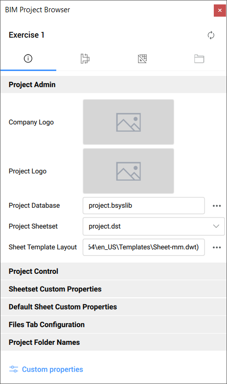
Info tab
Offers a complete overview about the current project.
Project Admin
Shows and sets the:
Company Logo: click the thumbnail to select a PNG file. A copy will be made in the project folder and will be renamed 'project.png'. For example, this can be used in a title block.
Note: The company logo will automatically update in the sheet views of the currently open sheet drawings after saving the open sheet drawings.
Project Logo: click the thumbnail to select a PNG file. A copy will be made in the project folder and will be renamed 'project.png'. For example, this can be used in a title block.
Project Database: click the browse button () to open the Project Database dialog box that gives a complete overview of the project's drawings and their stored and found database paths. The dialog box allows you to select another project database or to rename the current one. It also supports connecting the listed drawings to the project database.
Project Sheetset: displays the current sheet set. Click the drop-down arrow to select an available sheet set from the list.
Sheet Template Layout: click the browse button () to open the Select Layout dialog box where you can select the template drawing file path and a layout from the template file.
Project Control
Sets and shows the sheet set properties:
Project Name
Project Number
Project Phase
Project Milestone
Sheetset Custom Properties
Sets and shows the sheet set properties defined by the user (for example, Client City, Client Name, Client State, Client Street, Project City, Project State, Project Street).
Default Sheet Custom Properties
Sets and shows the sheet properties defined by the user (for example, Checked By, Drawn By).
Files Tab Configuration
Defines the folders and extensions to ignore. It allows you to specify what part of the project you want to see in the Files tab.
Project Folder Names
Sets the names of the project folders for components, details, images and schedules.
Custom properties
Opens the Custom Properties dialog box where Sheet Set and Sheets custom properties can be added, edited or deleted.
Sections and views tab
Displays a list of project sections organized by type. You can expand a section type to see its sections.
A context menu displays when you right-click a section:
Select Section Entity: selects the section entity in the project model drawing.
Note: This can also be done by double clicking the section entity.
Rename: renames the section entity.
Display Section Result: displays the section result in the corresponding sheet and zooms in on its viewport. If not already open, the drawing is opened.
Create Sheets: opens the Create Sheets dialog box that allows you to set the viewports and settings of the new sheet.
Note:
If a sheet is already created for the selected section, a notification pop-up will appear indicating the name of the sheet. This sheet can be edited in the panel's Sheets tab. Double click it or select the Edit Sheets option from the sheet's context menu.
BIM project data is now initialized with an XML file that can be edited by users.
Update Now: regenerates the section result.
Update in Background: regenerates the section result in background, without interrupting the user workflow.
Note: You can place sections (single/multiple items selection) or 3D views (single item selection) on an active sheet's Paperspace by dragging items from the Sections and views tab tree and dropping them to that sheet's Paperspace:
For single item selection, specify the insertion point. When placing a 3D view, right click before specifying the insertion point to display a context menu that allows you to select the viewport scale.
For multiple items selection, specify first the insertion point, then the second point of a rectangle that defines how the items are arranged (how many rows/columns).
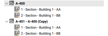
Sheets tab
Displays the contents of the project's sheetset. You can expand a sheet name to see its sheet views.
Note:
Double clicking a sheet will open the sheet drawing.
You can move a sheet view from one sheet to another by dragging and dropping it above the sheet's name. You can hold down the Ctrl key to drag a copy of that sheet view.
Details
Click the section name to expand it. The section will display the relevant properties for the selected items in the tab. If not grayed out, you can edit these properties.
Auto background updating
Updates the section results automatically, without interrupting the your workflow. It toggles the ENABLEBIMBKUPDATE system variable.
Add button
By pressing the Add button the below options are available:
New Sheet: opens the New Sheet(s) dialog box which allows you to add a new sheet to the Sheets tab or to the currently selected subset, if any.
New Subset: adds a new subset to the Sheets tab or to the currently selected subset, if any.
Status of the sheet views:
: the sheet view is updated.
Note: When you hover over the sheet view, a tooltip appears explaining the status and indicating the time the section was last updated:
: the sheet view is background updated.
Note: When you hover over the sheet view, a tooltip explaining the status appears:
When a 3D model is active:
Note:(n) shows the order in which background update will operate (is the index of the view in the queue).
When a sheet is active:
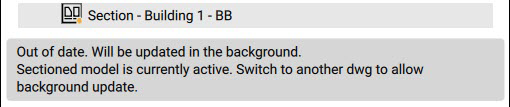
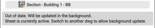
: the sheet view is out of date.
Note: When you hover over the sheet view, a tooltip explaining the status appears. It also indicates the time the section result block was last updated as well as the time the model was saved. In this way you can check whether the save time of the model is more recent than the update time of the sheet view:
when background update is on:
When a 3D model is active:
When a sheet is active:
: the sheet view has an error.
Note: When you hover over the sheet view, a tooltip explaining the status appears:
A context menu displays when you right-click on a sheet:
New Sheet(s)...: opens the New Sheet(s) dialog box that allows you to add a new sheet to the Sheets tab.
Open Sheet: opens the sheet drawing. You can also double click the sheet to open it.
Copy Sheet: makes a copy of the sheet dwg and the sheet entry in the sheetset (under the same subset). All blocks, viewports, named views and sheet views will be copied as well. The naming and numbering of the copied sheet will be handled automatically.
Edit Sheet: opens the Edit Sheets dialog box that allows you to edit the properties of the selected viewports.
Note: There is always an entire sheet opened in the dialog box. If you select a single sheet view, all the viewports of that sheet are listed and when a subset is selected, all sheets in the subset are shown.
Remove Sheet: removes the sheet.
Collect Details: collects all tagged details from the selected sheets and inserts the layouts of these details in the current sheet.
Update Now: cancels the queue that is currently running to update sheets and schedules the selected set of sheets as a new queue. The background updating continues once this queue finished updating.
Update in Background: updates the sheets view in background.
A context menu displays when you right-click a sheet view:
Display View: displays the corresponding result and zooms in on its viewport.
Edit Sheet: opens the Edit Sheets dialog box that allows you to edit the properties of the selected viewports.
Remove View/Result: removes the sheet view and corresponding result (viewport, viewlabel, sheetview, and result block, but only when no other viewport views it)
Update Now: updates the sheet view.
Update in Background: updates the sheet view in background.
Place view label: insert a view label in the current sheet and establish the link between view label and viewport. The new view label replaces the old one if the view label already exists.
Note: This action is available only when the current dwg tab is an opened sheet document.
You can easily place a sheet view to another active sheet's paperspace by dragging it from the Sheets tab and dropping it on the paperspace.
A context menu displays when you right-click a subset:
Remove Subset: removes the subset (only possible when it doesn't contain any sheets/subsets).
Files tab
Shows the contents of the project folder and allows you to place all supported files (by drag and drop) on an active drawing:
Drawings (models, sheets, ...)
Schedules, scripts, ...
Images:
Company logos, googlemap images, site photos, etc.
PNG created by script based on named views.
Renders created in Bricscad or Enscape, Twinmotion.
Note: Some of the supported files for import can only be placed in the active drawing’s Paperspace.
A context menu displays when you right-click a Detail:
Check details: launches the BIMCHECKDETAILS command.
Open: opens the detail file.
View detail: opens the View Detail dialog box.
Rename: allows you to rename the detail file.
Unmark as detail: unmarks the file as a detail.
Add references: launches the BIMADDDETAILREFS command to create a link between the master model and the detail file.
Duplicate: creates a duplicates file of the detail.
Delete: deletes the detail file.
Rename: renames the detail file.
A context menu displays when you right-click on a Sheet:
Duplicate: creates a duplicate of the sheet.
Delete: deletes the selected sheet.
Rename file: opens the Rename Sheet dialog box that allows you to rename the sheet.
Note: If the linked sheets contain the name of the file, the linked sheets' number and title are automatically renamed. You can override the automatic renaming before closing the dialog box.
A context menu displays when you right-click a drawing:
Mark as master model: makes the drawing a master drawing. This means any sections or 3D views defined in the drawing or any of its Xrefs will be listed in the Sections and views tab.
Note: It is allowed to have multiple master drawings.
Duplicate: creates a duplicate of the drawing.
Delete: removes the drawing from the files explorer.
Rename file: opens the Rename drawing dialog box where you can enter a new name for the drawing.
Note: You can drag and drop a DWG or a DXF file from the Files tab into the current drawing. You can then choose the insertion method (copy the file content or insert it as a block or xref).
A context menu displays when you right-click a Master model:
Unmark as master model: the selected model is no longer a Master model.
Duplicate: creates a duplicate of the Master model.
Delete: deletes the selected Master model
Rename file: opens the Rename drawing dialog box that allows you to rename the Master model. All related are automatically renamed as well.
A context menu displays when you right-click a BOM file in the Schedule folder:
Open file: opens the Schedule file on a BOM reader on your computer where you can edit and save the file.
Generate csv: generates a CSV file from the BOM file. The CSV file is located in the same schedules folder as the original BOM file.
Generate xlsx: generates an XLSX file from the BOM file. The XLSX file is located in the same schedules folder as the original BOM file.
Duplicate: creates a duplicate of the BOM file.
Delete: removes the BOM file.
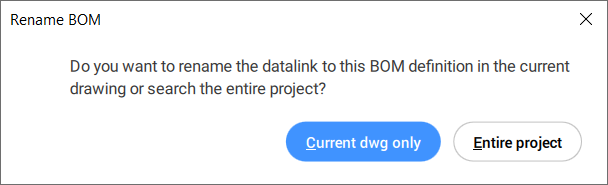
Rename file: opens the Rename BOM file dialog box where you can enter a new name for the file. Click Rename to open the Rename BOM dialog box. Here you can choose to rename the file in the Current dwg only or in the Entire project.
Note: Renaming the datalink to the BOM definition in the entire project can take longer than renaming it in the current drawing.
Note: The BIM Project Browser panel supports the old schedules workflow. You can add DXD files manually to the Schedules folder. When a DXD file is present in the Schedules folder, its context menu displays the same options as for a BOM file.
When you right-click a CSV or XLSX file a context menu displays:
Create table: inserts the table in the current sheet using a Datalink.
Duplicate: creates a duplicate of the CSV or XLSX file.
Delete: deletes the selected CSV or XLSX file.
Note: when you double click the CSV or XLSX file the file opens in an application set by the system.
Rename file: opens the Rename file dialog box where you can enter the new name for the CSV or XLSX file.
Note: You can place a BOM schedule on a currently opened sheet’s Paperspace by dragging the BOM file from the Schedules folder in the Files tab tree and dropping it onto that sheet's Paperspace. This generates a table with a datalink to the BOM file. You can update the BOM schedule later on using the DATALINKUPDATE command.
A context menu displays when you right-click a script file:
For python script files:
Run script: executes the python script.
Open with default program: opens the python file (PY) with default program.
Duplicate: creates a duplicate of the PY file.
Delete: removes the python file.
Rename file: opens the Rename file dialog box where you can enter the new name for the file.
For LISP files:
Load script: loads and executes the lisp script.
Duplicate: creates a duplicate of the LISP file.
Delete: removes the lisp (LSP) file.
Rename file: opens the Rename file dialog box where you can enter the new name for the LISP file.
for any other file type: double click to open the file with an application set by the system.
A context menu displays when you right-click a typed plan file:
Open folder: opens the folder on your computer where the typed plan is located.
Duplicate: creates a duplicate of the typed plan.
Delete: removes the typed plan file.
Note: Double click a typed plan to open the BIM Typed Plan Editor dialog box that allows you to edit it.
Rename file: opens the Rename typed plan dialog box where you can enter a new name for the file.
By pressing the add button the below options are available:
New DWG
Opens the Choose name dialog box to add a new DWG drawing to the file.
Import DWG
Opens the Select dwg to import dialog box to import an existing DWG into the files.
New BOM
Opens the Where should the file be created? dialog box to create a new BOM table template.
Import BOM
Opens the Select BOMs to import dialog box that allows you to import the BOMs.
New Typed Plan
Opens the BIM Typed Plan Editor dialog box that allows you to create a drawing customization.
Import Typed Plan
Opens the Select a Typed Plan to import dialog box to import an already defined drawing customization.
Import script
Opens the Select Scripts to import dialog box from which can import a Python, Lisp or Grasshopper script.
Import Templates
Opens the Select templates to import dialog box from which you can choose a template to import.
Create Detail [Beta]
Launches the BIMCREATEDETAIL command.
Import Detail [Beta]
Opens the Select dwg to import as detail dialog box from which you can choose a drawing to import as detail.


 ) to open the Project Database dialog box that gives a complete overview of the project's drawings and their stored and found database paths. The dialog box allows you to select another project database or to rename the current one. It also supports connecting the listed drawings to the project database.
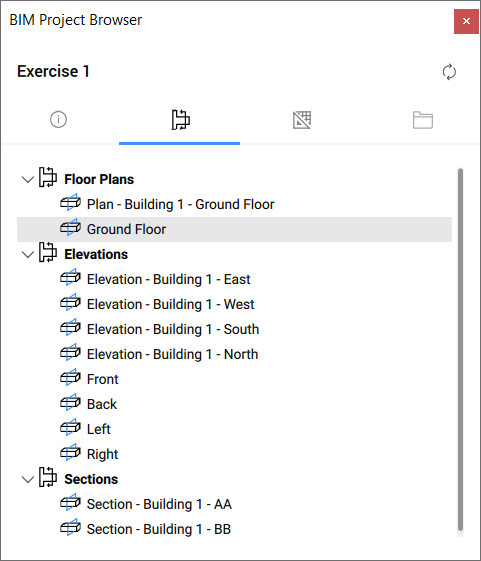
 : the sheet view is updated.Note: When you hover over the sheet view, a tooltip appears explaining the status and indicating the time the section was last updated:
 : the sheet view is background updated.Note: When you hover over the sheet view, a tooltip explaining the status appears:
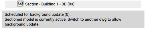 Note: (n) shows the order in which background update will operate (is the index of the view in the queue).
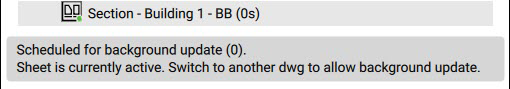
 : the sheet view is out of date.Note: When you hover over the sheet view, a tooltip explaining the status appears. It also indicates the time the section result block was last updated as well as the time the model was saved. In this way you can check whether the save time of the model is more recent than the update time of the sheet view:
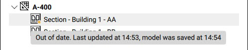

 : the sheet view has an error.Note: When you hover over the sheet view, a tooltip explaining the status appears:
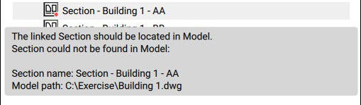
 Note: Renaming the datalink to the BOM definition in the entire project can take longer than renaming it in the current drawing.Note: The BIM Project Browser panel supports the old schedules workflow. You can add DXD files manually to the Schedules folder. When a DXD file is present in the Schedules folder, its context menu displays the same options as for a BOM file.