


VIEWSECTIONSTYLE command
Opens the Drawing explorer dialog box with View Section Styles selected.

Icon: 
Description
Opens the Drawing explorer dialog box with View Section Styles category selected to view and modify view section styles in the current drawing.
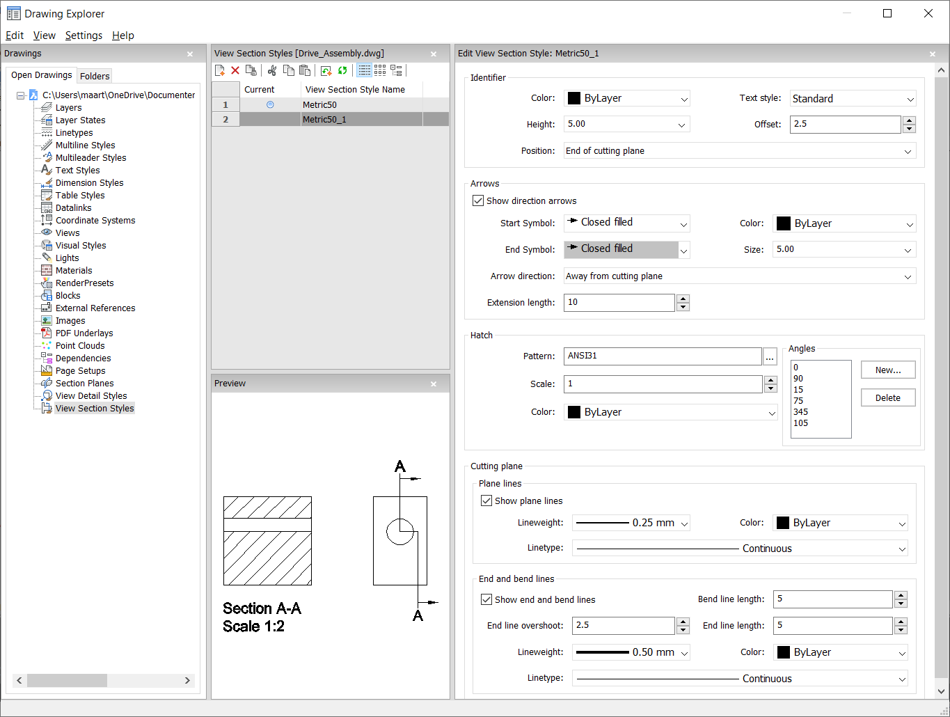
Options within the command
- Identifier
- Sets the properties of the section identifier.
- Color
- Specifies the color of the identifier.
- Text Style
- Specifies the text style used by the identifier text. To employ a different text style, use the STYLE command to create it.
- Height
- Specifies the height of the identifier.
- Offset
- Specifies the distance from the end of the cut lines to the arrow.
- Position
-
Determines where the identifiers are located.
- End of cutting plane: places the identifiers at the ends of the cutting lines.
- Above direction line: places the identifiers outside the detail's boundary and draws a leader from the parent view to the detail. No symbol is used.
- On boundary: places the identifiers on the detail's boundary.
- On boundary with leader: places the identifier on the detail's boundary and draws a leader from the parent view to the detail.
- Arrows
-
Sets the properties of the section arrows.
- Show direction arrows: toggles the display of the arrows
- Start Symbol: specifies the look of the start symbol
- Color: specifies the color of the arrow
- End Symbol: specifies the look of the end symbol
- Size: specifies the size of the arrow
- Arrow direction: points the arrow towards or away from the cutting line
- Extension length: determines the length of the "dimension" line on the arrows
- Hatch
-
Sets the properties of the section hatching.
- Pattern: choose a pattern name from the drop-down list.
- Browse: displays the Hatch Pattern Palette dialog box, from which you choose a pattern visually.
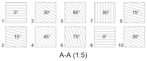
- Angles: sets the angle for the pattern, one angle for subsequent cuts.
The first angle in the list is applied to the first solid, the second
angle to the second, and so on. When there are more solids to cut than
angles listed, then the program starts again from the first angle. See
figure below.
- New: adds angles to the list. Displays the New Hatch Angle dialog box, in which you enter an angle.
- Delete: deletes the selected angle from the list.
- Scale: specifies the scale of the pattern.
- Color: specifies the color of the pattern.
- Cutting Plane | Plane Lines
-
Sets the properties of the cutting plane lines.
- Show plane lines: toggles the display of the lines.
- Lineweight: specifies the weight of the lines.
- Color: specifies the color of the lines.
- Linetype: specifies the pattern of the lines.
- Cutting Plane | End and Bend Lines
-
Sets the properties of the end and bend lines.
- Show end and bend lines: toggles the display of the lines.
- Bend line length: specifies the distance the bend line offsets from one cut line to another.
- End line overshoot: specifies the distance from the section to the end of the plane line.
- End line length: specifies the length of the end lines.
- Lineweight: specifies the weight of the lines.
- Color: specifies the color of the lines.
- Linetype: specifies the pattern of the lines.
Context Menu Options
- New
- Creates a new view detail style as a copy of the currently selected style.
- Delete
- Removes the selected style from the drawing.
- Rename
- Renames the selected view section style.
- Select All
- Selects all view section style definitions.
- Invert selection
- Deselects the current selection and vice versa.