Using drag
Commands
DRAG
About
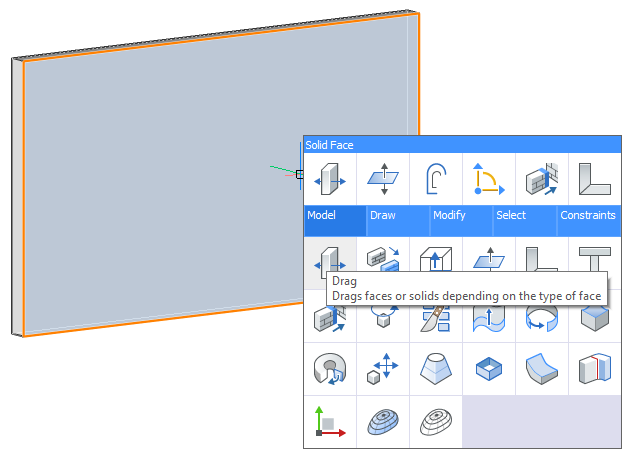
The Drag tool allows you to move walls, slabs or linear elements on the highlighted face of a solid. For instance, the Drag tool can be used to move linear solids by highlighting/selecting the end or side face of a linear solid. Depending on the modeling operation, the connection between solids can be either preserved while dragging one or more solids at a time or solid (s) can be moved independently by disjoining the connectivity to other solid(s).
Procedure: using drag on a 3D solid
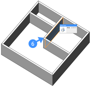
- Highlight/select any faces of the solid and select Drag from the tab.
- Move the cursor to adjust the position of the moving solid in the dynamic dimension field, then click or enter a precise value in the dynamic dimension field and press Enter.
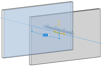
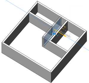
Note: A ruler appears to visually represent the distance over which you will move the entity. - The Hotkey Assistant appears at the bottom of the screen showing the available options.

Note: The current mode is indicated by a blue frame.Hit the CTRL-key to toggle the connectivity mode. Alternatively, type D+Enter to disable connectivity or type E+Enter to enable connectivity.- Select the Enable connectivity mode option, to move the solid while preserving the connections between solids.
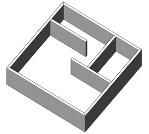
In the following illustration, the solid behavior is shown before and after applying the DRAG in Enable connectivity mode. The connectivity between walls, i.e. T- (3) and mitered (4) connections are preserved after dragging an inner wall surface (5).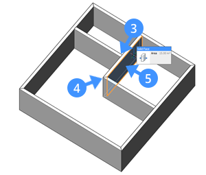
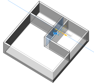
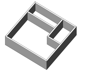
- Select the Disable connectivity mode (default) option to move the solid while breaking the connections between solids.In the following illustration, the solid behavior is shown before and after applying the Drag in "Disable connectivity mode". The connectivity between walls, i.e. T- (3) and L- (6) connections are disjointed after dragging an inner wall surface (5).