


Civil Explorer panel
Icon: 
Description
Civil Explorer is the main panel to manage and access Civil entities. Entities are arranged in a tree view and grouped by entity type.
Through this panel, you can access settings and properties of Civil entities and allows you to edit existing and add new entities and their components.
The panel is divided into two parts. The upper part with list of entities in a tree view, and the bottom part with additional properties, depending on the selection in the tree view.
The Civil Explorer panel is the core panel for Civil design. In the Civil Workspace, click the Civil Explorer icon in the Ribbon under the Home tab to toggle the panel on/off.
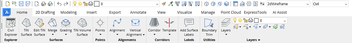
Use the drop-down list at the top of the Civil Explorer to toggle between the Object view and the Settings view.
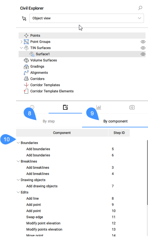
Object view
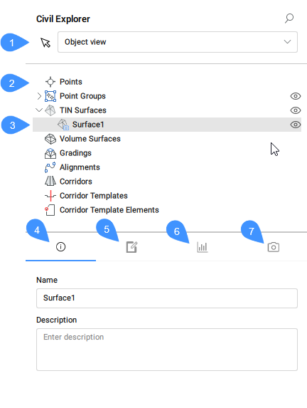
The Object view category of the Civil Explorer panel enables you to manage and access Civil entities in the current drawing.
- Pick a Civil object
- Civil object types
- Selected Civil object
- Info
- Definitions
- Statistics
- Visual Styles
- Pick a Civil object
- Pick a Civil object in the drawing.
- Civil object types
- Lists all Civil objects that currently exist in BricsCAD® Civil. Right clicking on a civil object type opens a context menu that contain Create option which launches specific commands to create a selected object.
- Selected Civil object
- Highlights the selected Civil object in a tree-view.
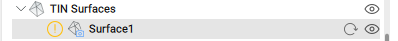
For TIN Surface objects the following status icons are available: Show/Hide, Out of Date, Refresh and Snapshot.
- Info
- Displays information about the selected Civil object (Name and Description). Both can be edited.
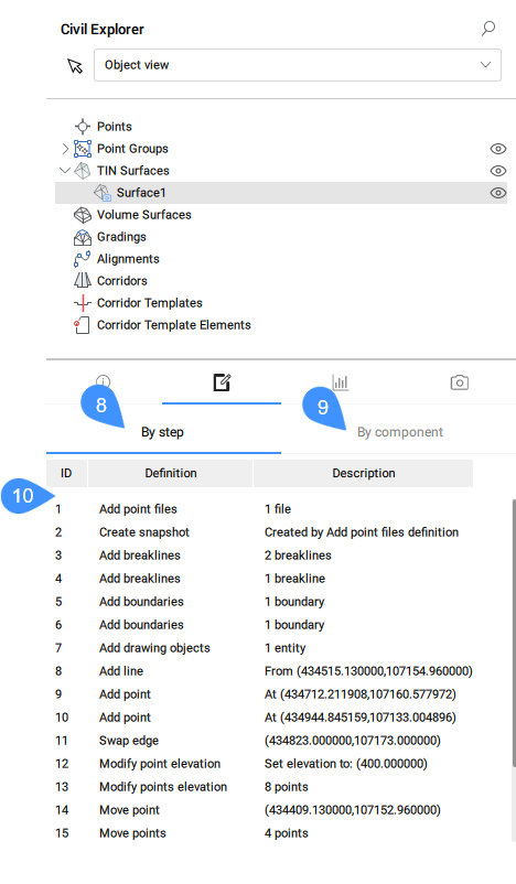
- Definitions
- It shows the components (source data) from which the TIN surface was built, the editing operations used, and the chronological order in which definitions were added. You can switch view by selecting the By component or the By step tab.
-
-
- List of all definitions/components used to create a TIN Surface
- Lists all TIN surface definitions. The context menu offers the possibility to change the order of definitions and to Delete them. Additionally, for most TIN Surface definitions, there are the options Select and Zoom to, which makes finding them in the drawing very easy. Double clicking a definition or pressing Edit option from the context menu opens the Surface: Surface x, Definition step ID: y dialog box which displays all details for the selected definition. You can edit the definition parameters.
-
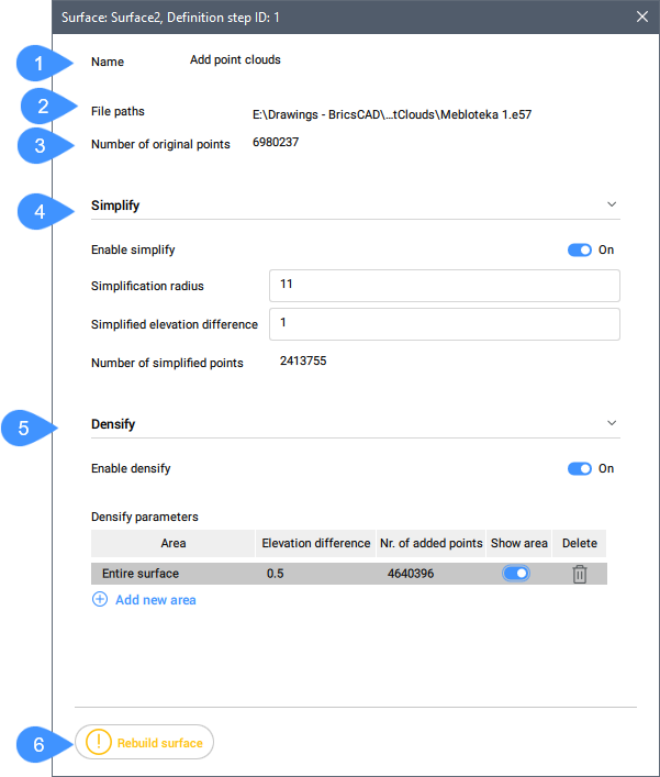
- Name: displays the surface definition name, Add point file.
- File paths: displays the file path. By pressing the browse icon, the Select surface file dialog box is opened.
- File format: displays the file format used for point file.
- Simplify: if enabled, allows the user to change the simplification parameters.
- Densify: if enabled, you can manage the densify parameters and add new densify areas.Note: Editing the Simplify and Densify parameters simultaneously without surface rebuilding after each edit is possible.
- Rebuild surface: rebuilds the surface.Note: This button appears only when editing the Simplify and Densify parameters.
By editing an Add breaklines definition, the below Surface: Surface x, Definition step ID: y dialog box opens:
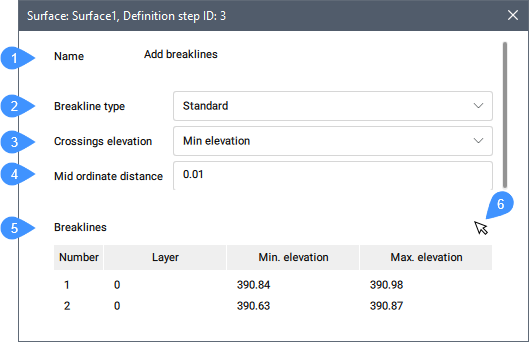
- Name: displays the surface definition name, Add breaklines.
- Breakline type: displays the selected breakline type (Standard or Projected).
- Crossings elevation: displays the selected crossing elevation.
- Mid ordinate distance: sets the mid ordinate distance.
- Breaklines: lists the breaklines in the drawing, their layers, min. and max elevation. The context menu offers the possibility to Zoom to, Select, Remove a breakline, or to copy geometry to clipboard.
- Pick button: picks breakline in the drawing to select it in the table.
By editing an Add boundaries definition, the below Surface: Surface x, Definition step ID: y dialog box opens:
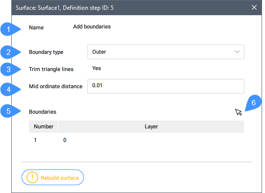
- Name: displays the surface definition name, Add boundaries.
- Boundary type: displays the selected boundary type.
- Trim triangle lines: displays the status of the trim triangle lines.
- Mid ordinate distance: sets the mid ordinate distance.
- Boundaries: lists the boundaries in the drawing and their layers. The context menu offers the possibility to Zoom to, Select or Remove a boundary.
- Pick button: picks boundary in the drawing to select it in the table.
By editing an Add drawing objects definition, the below Surface: Surface x, Definition step ID: y dialog box opens:
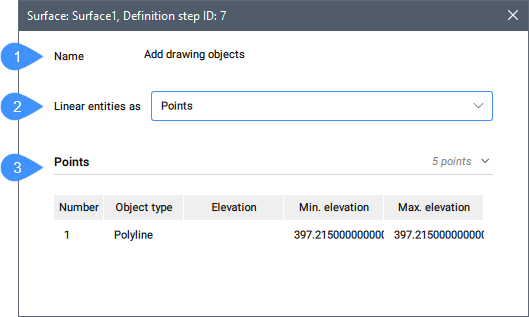
- Name: displays the surface definition name, Add drawing objects.
- Linear entities as: displays the selected entity type.
- Points: lists the objects with their properties. The context menu offers the possibility to Zoom to the object in the drawing or to copy to clipboard the object geometry information.
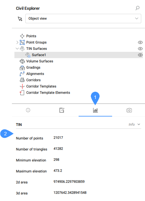
- Statistics
- The Statistics tab displays the statistics for the selected TIN surface (number of points and triangles, minimum and maximum elevation, 2d and 3d area).
-
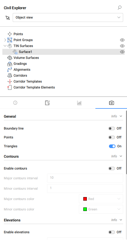
- Visual styles
- The Visual styles tab allows you to change the general visual style, the visual style of the contours, the visual style of the elevations and the visual styles of the slopes in the case of a TIN surface.
-
Settings view
The Settings view category of the Civil Explorer panel manages the civil entity styles and formats.
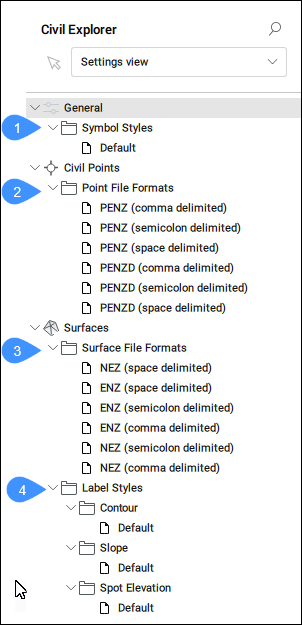
- Symbol styles
- Point file formats
- Surface file formats
- Label styles
- Symbol styles
- Lists the available symbol styles. You can create, edit, copy, or delete a symbol style. By pressing the corresponding option from the context menu, the Symbol Style dialog box opens.
- Point File Formats
- Lists the available point file formats. The list can be managed by double-clicking or pressing the Edit option from the context menu which opens the Manage Point File Formats dialog box.
- Surface File Formats
- Lists the available surface file formats. The list can be managed by double-clicking or pressing the Edit option from the context menu which opens the Manage Surface File Formats dialog box.
- Label styles
- Lists the available label styles for Contour, Slope and Spot elevation. The context menu allows you to Edit, Copy, or Delete a label style. Edit and Copy options open the Label Style Editor dialog box which allows you to define a new label style.