Selecting BIM entities
About
When you hover over an object in BricsCAD, the object is highlighted. When you left click a highlighted entity, it will be selected.
Highlighting: you only can highlight one entity at once.
Selecting: you can select as many entities as desired.
You can perform most of the modeling process by highlighting the entity and using the Quad. For example, when you highlight a surface, the Quad will open. You can pick the command you want, without selecting the surface first.
Selection modes
The selection modes allow you to control which sub-entities (faces, edges, and boundaries) of a 3D solid are highlighted in the selection preview and can be selected.
To access the Selection modes options, do one of the following:
- Open to access the SELECTIONMODES system variable options.
- Launch the SELECTIONMODES system variable in the Command line to set its value.
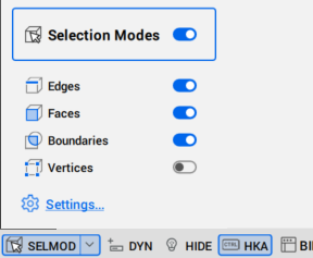
- Status bar: turn On the Selection Modes options.
- Ribbon:
Note: To display the Ribbon, right-click on a toolbar and choose in the context menu. - Toolbar: To display the Selection Modes, right-click on a toolbar and choose in the context menu.

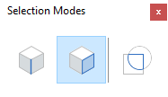
The available selection modes are:
- Select edges (
 ): controls whether 3D solid edges are highlighted by selection preview and can be selected. Click on a 3D solid edge to select it.
 - Select faces (
 ): controls whether 3D solid faces are highlighted by selection preview and can be selected. Click on a 3D solid face to select it.
 - Select detected boundaries (
 ): controls whether closed boundaries in XY-plane of the current coordinate system or on the face of 3D solids are detected. Click on the closed boundary from a face of the 3D solid to select it.
 - Select vertices (
 ): controls whether 3D solid vertices are highlighted by selection preview and can be selected. Click on the vertices of the 3D solid to select them.
 - Disable selection modes: disables all selection mode options. Also, toggles the activation of the Selection Modes in the Status bar.
- Display Sides and Ends (
 ): controls the bimSides and BimEnds visibility of all linear elements.Note: The Display Sides and Ends option is only available on classified linear elements with the attached library profile.
Changing selection modes setting
A sub-entity is a face, edge or boundary of a 3D solid. To control which sub-entities you select in your model, do one of the following:
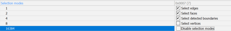
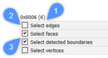
- Open the Settings dialog box with the SETTINGS command and find Selection Modes section. The following illustration shows the sum of the values (1) of the SELECTIONMODES system variable when the Select edges and Select vertices options are disabled (2) after clicking the checkbox once; and the Select faces and Select detected boundaries are enabled (3).
- Type SELECTIONMODES in the Command line and change the current parameter.
- Use the Ctrl key on the keyboard to temporarily toggle between the different selection modes. These key functions enable you to select any type of entity.
To display the BimSides/Ends for linear elements you can use the DISPLAYSIDESANDENDS system variable in the Settings dialog box or set the DISPLAYSIDESANDENDS system variable to 1 in the Command line.
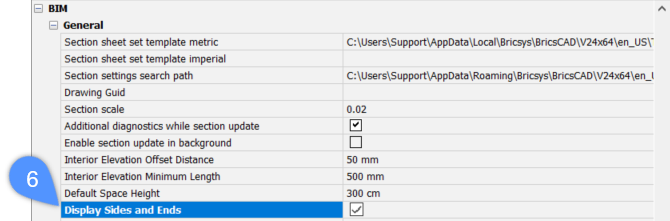
The following illustration shows the BIM, General system variable when the Display Sides and Ends option is ticked (6) after clicking the checkbox once.
Selecting sub-entities
When Select edges is off, Select faces is on, Boundary Detection is on, do one of the following:
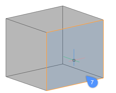
- To highlight a solid face, hover over the face with your mouse cursor. The highlighted face is displayed in orange (7). To select the face, left-click it when the face is highlighted. To select multiple faces of the solid, left-click them one by one.
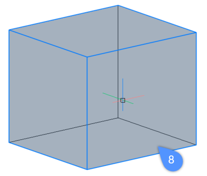
- To highlight a solid, hover over one of its faces while holding down the CTRL-key. The solid is displayed in blue (8). To select the solid, left-click it while the solid is highlighted. To select multiple solids left-click them one by one.
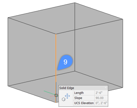
- To highlight an edge, hover over the edge of the solid while holding down the CTRL-key. The edge is displayed in orange (9). To select the edge, left-click it while the edge is highlighted. To select multiple edges left-click them one by one.
- To highlight a boundary, hover over the detected boundary on the face of the 3D solid.
When the detected boundary is highlighted, it is displayed in a color. By default, inside of the boundary is displayed in green (10) and the outer edge of the boundary is displayed in blue (11).
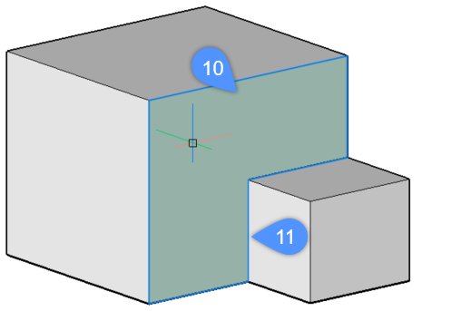
Note: This setting can be changed by typing BOUNDARYCOLOR on the Command line (default value = 95).
Procedure: modifying the thickness of a solid
- Make sure the Select faces option of the SELECTIONMODES system variable is selected.
- Hover the cursor over the face of a solid.
If necessary, press Tab to highlight an obscured face.
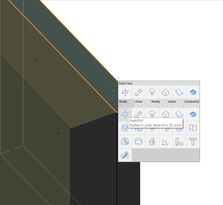
- When the face highlights, choose Push/Pull in the Model command group of the Quad.
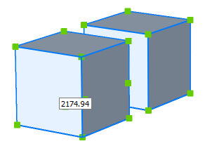
- The selected face of the solid is dragged.
The dynamic dimension field displays the relative displacement of the face (= with respect to its original position).
- (Optionally) Press the Tab key to change the face selected as the reference face for the dynamic dimension.Note: When a composition with locked thicknesses (non-variable thickness) is applied to a solid and if the thickness of the solid is not equal to the total amount of the composition thickness, the solid is displayed with red hatches. Execute the BIMUPDATETHICKNESS command to re-apply the composition to such solid.
Procedure: modifying the height of a wall
Modify the dimensions of a single wall
- Make sure the Select faces option of the SELECTIONMODES system variable is selected.
- Hover the cursor over the top face of the wall.
If necessary, press the Tab key to highlight an obscured face.
- When the face highlights, choose Push/Pull in the Model command group of the Quad.
The selected face moves dynamically with the cursor.
The dynamic dimension fields display the incremental height.
- Do one of the following:
- Type a value in the dynamic dimension field and press Enter.
- Press Tab to use another reference face, e.g. the bottom face of the solid, then type a value in the dynamic dimension field.
Modify the height of multiple walls
Use the SELECTALIGNEDFACES command (:  ) to select the top face of all solids in the same horizontal plane.
- Make sure the Select faces option of the SELECTIONMODES system variable is selected.
- Move the cursor over the top face of one of the walls.
If necessary, press the Tab key to highlight an obscured face.
- When the face highlights, choose SELECTALIGNEDFACES in the General command group in the Quad.
All faces lying in the plane of the selected face are selected.
- Now follow the same steps as for a single wall.
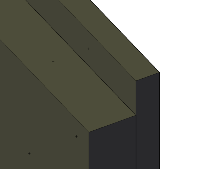
Modify the height ply-by-ply
When the Display Composition property of a solid is set (LEVELOFDETAIL system variable =2 and, optional, RENDERCOMPOSITIONMATERIAL system variable =1), and the Select faces option of the SELECTIONMODES system variable is selected, the height or length of the composition plies can be modified separately.
- Move the cursor over the ply that you want to edit and choose Push/Pull in the Model command group of the Quad when the ply highlights.
- Type value in the dynamic distance field.
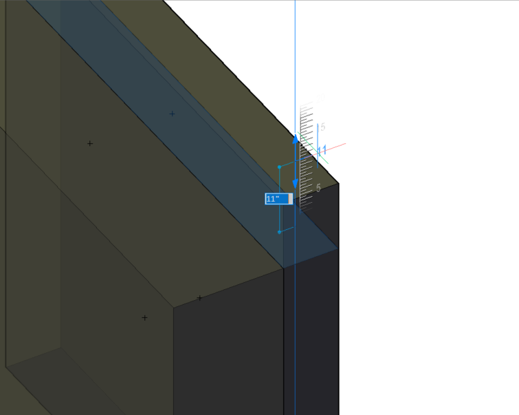
- Press Enter to accept the distance.
Selecting obscured sub-entities
In your drawing, some entities or sub-entities (faces, edges, and boundaries) might be hidden behind other entities. The Tab key enables you to cycle through sub-entities.
The following steps show how to highlight a hidden face that lies beneath the cursor.
When Select edges is off, Select faces is on, Select detected boundaries is on.
- Place your cursor on one of the solid faces.
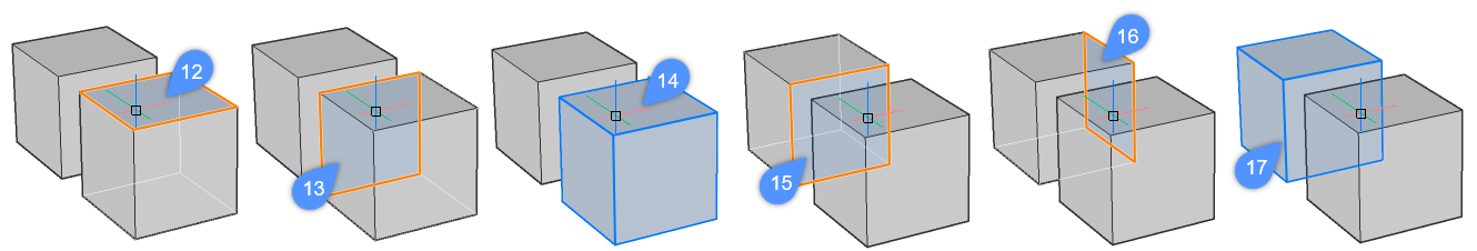
In the example below, the top face of the front solid is highlighted (12).
- Press the Tab key to cycle through the hidden entity.
The back face of the front solid is highlighted (13).
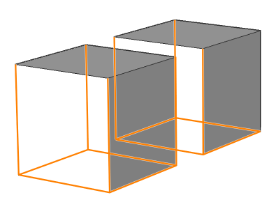
- Repeatedly pressing the Tab key while keeping the cursor at the same position allows you to highlight the entire solid in the front (14) and the front face (15) and right face (16) of the rear solid. Finally, the entire rear solid is highlighted (17).
- When the entity or sub-entity that you want to select is highlighted, left-click it to select.
Selecting multiple entities using the selection boxes
The selection boxes allow you to select one or more than one entity at once. To use a selection box, left-click on an empty space in the drawing area and move the cursor until the selection box covers the entities that you want to select.
There are two types of selection boxes in BricsCAD:
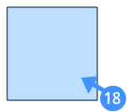
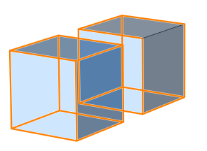
A blue selection box (18) appears when you create a box from left to right. The blue selection box will only select entities that are entirely covered by this selection box.
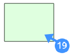
A green selection box (19) appears when you create a box from right to left. The green selection box will select all elements that are entirely covered by the selection box and all the elements that intersect with one of the edges of the box.
The following steps show how to select multiple entities using the blue selection box:
- Click and move the mouse to the right to create a blue box around the entities you want to select. When the entity is completely inside the window, it will be added to the selection set.
The example below shows the blue selection box usage when the selection mode is set to Solids (default).
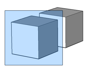
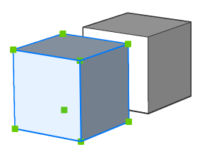
The blue selection box covers the left cube completely and therefore only this cube is selected in the model.
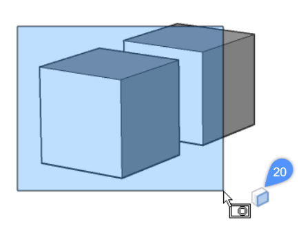
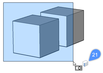
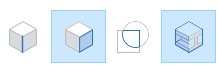
- To select faces of 3D solids and surfaces, press the Ctrl key once during window selection. The icon (20) next to the cursor indicates the selection mode. The faces that are completely inside the window will be selected when the selection mode is set to Select faces.
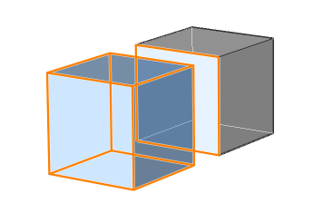
- To select edges of 3D solids and surfaces, press the Ctrl key twice during window selection. The Select edges icon (21) appears next to the cursor. The edges that are completely inside the window will be selected when the selection mode is set to Select edges.
The following steps show how to select multiple entities using the green selection box:
- Click and move the mouse to the left (crossing window) to create a green box around the entities you want to select. When the entities overlap with the window or are completely inside the window, they will be added to the selection set.
The example below shows the green selection box usage when the selection mode is set to default:
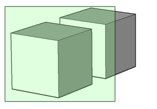
The green selection box selects both cubes in the model as the selection box overlaps with the two cubes.
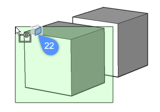
- To select faces of 3D solids and surfaces, using of the green selection box, press the Ctrl key once during window selection. The Select faces icon appears next to the cursor (22). Any faces that are completely or partially inside the crossing window will be selected.
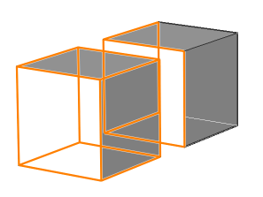
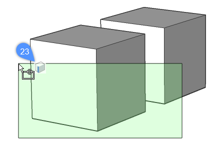
- To select edges of 3D solids and surfaces, using of the green selection box, press the Ctrl key twice during window selection. The Select edges icon appears next to the cursor (23). Any edges that are completely or partially inside the crossing window will be selected.
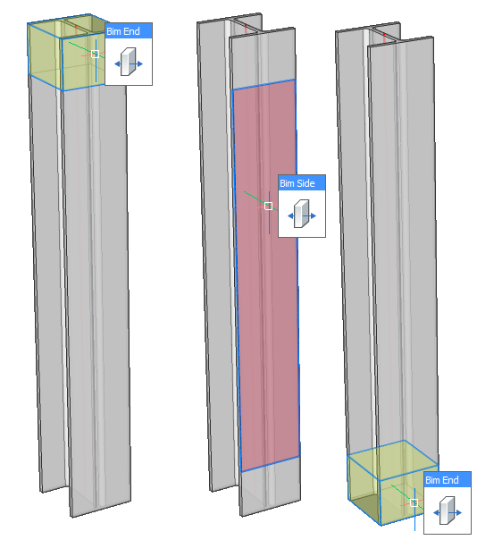
Selecting/highlighting BIM sides and ends on profiles
- Click the Display Sides and Ends icon in the BIM Toolbar.
- Hover over the linear solid in the model space when the cursor is on the top or on the bottom side of the linear solid. The Bim End face displays in yellow whereas the Bim Side face of the linear solid displays in red.