Inserting and editing windows and doors
About

For more information, visit the Command reference articles BMINSERT and -BMINSERT.
The -BMINSERT command is launched automatically when a component is dragged from the Library panel to the 3D model.
You can insert components in a floor plan, such as windows and doors, or to add and trim walls from a 2D orthographic view as well as a 3D view.
Inserting a window (or door)
-
Open the Library panel.
-
Make sure the Bricsys Bim library is selected in the Library menu.
-
Click the Windows folder.
-
Click the icon of the window you want to insert.
The Properties panel displays.
The window is attached to the cursor (1).

-
(option) Under Inserted Components Properties, edit the parameters of the window in the Properties panel.
-
Move the window over the face of a wall solid.
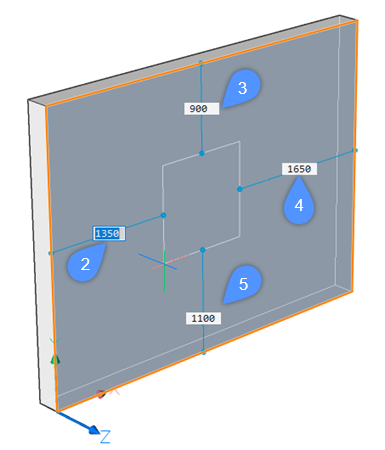
The solid face highlights and the distances from the insert to the nearest parallel edges of the parent solid (2, 3, 4, 5) are displayed:
-
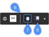
(option) Press the Ctrl key to switch from the Pick position mode (7) to the Change parameters mode (8) in the Hot Key Assistant widget (6) and adjust the width and height of the window.
Press the Tab key to switch between the width (9) and height (10) fields.
Press the Ctrl key to confirm the dimensions. This will switch back the widget mode to Pick position.

- Do one of the following:
-
Specify a point to insert the window.
-
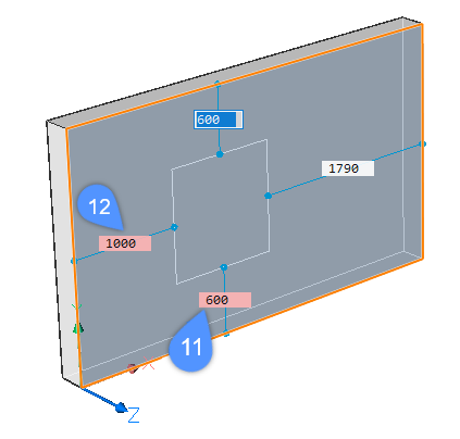
Type a value in the desired dynamic dimension field and press the Tab key to jump to the next field. The dimension field turns red to indicate it is locked (11, 12).
Press Enter to insert the window.
-
-
(option) Select the window to adjust its position in the wall. See Moving an insert section.
Inserting a copy of an insert
-
Hover over the insert and choose BIM insert in the Modify tab of the Quad.
The insert is attached to the cursor.
-
Proceed from step 6 in the previous procedure.
Editing the parameters of an insert
Parameters defined in the window or door source drawing allow you to edit each detail of a window/door separately.
-
Select the insert in the drawing. The current values of the various parameters are displayed in the Parameters section of the Properties panel.

-
Select a parameter and type a value in the settings field.
Moving an insert
- Using distance fields and reference points of the selection dimensions.
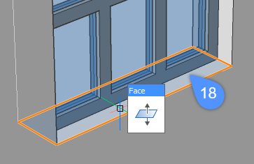
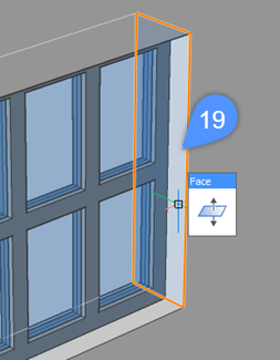
- Using the DMPUSHPULL command.
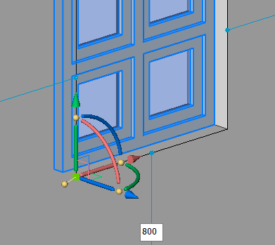
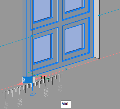
- Using the Manipulator.
- Using distance fields and reference points of the selection dimensions
-
-
Select the insert in the model.
Distances from the insert to the nearest parallel edges of the parent solid are displayed, as well as their respective reference points (13, 14, 15, 16):

- (optional) To show the distance from the insert to other points than those automatically detected, move the position of the reference points as needed (17).
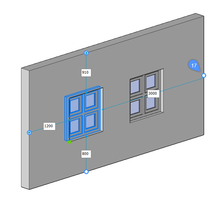
- Click a distance field, type in a value and press Enter.
-
- Using the DMPUSHPULL command
-
Note: Enable Select faces for SELECTIONMODE system variable.
- Using the Manipulator
-
Note: Set the value of the MANIPULATOR system variable to 2.
Replacing an insert
Use the BMREPLACE command to replace an insert.
The command allows you to replace:
- An insert from a file.
You can select a source file in a dialog box.
- A similar insert in the model.
The command prompts you to replace either the selected insert only, or all similar inserts in the entire model. The Parameter changes option allows you to either keep the original values or to apply the values of the replacement insert.


